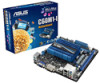

C60M1-I User's Manual
Page 11
... wrist strap or touch a safely grounded object or a metal object, such as the power supply case, to page x for buying an ASUS® C60M1-I Onboard LED Chapter 1: Product introduction 1-1 Failure to do so may cause severe damage to indicate that the system is a reminder that the... in the bag that came with a standby power LED that lights up to the motherboard, peripherals, or components. SB_PWR C60M1-I ON OFF Standby Power Powered Off C60M1-I motherboard! Refer to avoid damaging them . • Whenever you uninstall any motherboard component. Standby Power LED The motherboard ...
... wrist strap or touch a safely grounded object or a metal object, such as the power supply case, to page x for buying an ASUS® C60M1-I Onboard LED Chapter 1: Product introduction 1-1 Failure to do so may cause severe damage to indicate that the system is a reminder that the... in the bag that came with a standby power LED that lights up to the motherboard, peripherals, or components. SB_PWR C60M1-I ON OFF Standby Power Powered Off C60M1-I motherboard! Refer to avoid damaging them . • Whenever you uninstall any motherboard component. Standby Power LED The motherboard ...
C60M1-I User's Manual
Page 12
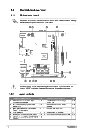
... DDR3 DIMM slots 1-3 10. Front panel audio connector (10-1 pin AAFP) 1-11 6. USB 2.0 connectors (10-1 pin USB78, USB910, 1-12 USB1112) 1-2 ASUS C60M1-I /O AMD® Fusion APU C-60 with RadeonTM HD 6290 graphics ICS 9LRPS482 DVI CHA_FAN USB34 AMD® FCH A50M (Hudson M1) LAN1_USB12 RTL 8111F 32Mb... C-60 with external ports goes to the rear part of the chassis. 12 3 4 17cm(6.7in) KB_USB56 EPU ATX12V Lithium Cell CMOS Power VGA C60M1-I DDR3 DIMM1 (64bit, 240-pin module) DDR3 DIMM2 (64bit, 240-pin module) EATXPWR 17cm(6.7in) CPU_FAN Super I Standby power LED (SB_PWR)...
... DDR3 DIMM slots 1-3 10. Front panel audio connector (10-1 pin AAFP) 1-11 6. USB 2.0 connectors (10-1 pin USB78, USB910, 1-12 USB1112) 1-2 ASUS C60M1-I /O AMD® Fusion APU C-60 with RadeonTM HD 6290 graphics ICS 9LRPS482 DVI CHA_FAN USB34 AMD® FCH A50M (Hudson M1) LAN1_USB12 RTL 8111F 32Mb... C-60 with external ports goes to the rear part of the chassis. 12 3 4 17cm(6.7in) KB_USB56 EPU ATX12V Lithium Cell CMOS Power VGA C60M1-I DDR3 DIMM1 (64bit, 240-pin module) DDR3 DIMM2 (64bit, 240-pin module) EATXPWR 17cm(6.7in) CPU_FAN Super I Standby power LED (SB_PWR)...

C60M1-I User's Manual
Page 14
...651.85V DIMM socket support 1 DIMM 2 DIMM • • • • • • • • (continued on the next page) 1-4 ASUS C60M1-I Motherboard Qualified Vendors Lists (QVL) DDR3-1066 MHz capability Vendors Part No. DIMM socket support (Optional) 1 DIMM 2 DIMM • • • • &#...we recommend that you install the memory modules from the blue slots for the OS can be about 3GB or less. C60M1-I Size SS/ DS A-DATA A-DATA A-DATA A-DATA A-DATA AD31333001GOU AD3U1333C2G9 AM2U139C2P1 AX3U1333C2G9-BP AD31333G001GOU 1GB SS 2GB SS ...
...651.85V DIMM socket support 1 DIMM 2 DIMM • • • • • • • • (continued on the next page) 1-4 ASUS C60M1-I Motherboard Qualified Vendors Lists (QVL) DDR3-1066 MHz capability Vendors Part No. DIMM socket support (Optional) 1 DIMM 2 DIMM • • • • &#...we recommend that you install the memory modules from the blue slots for the OS can be about 3GB or less. C60M1-I Size SS/ DS A-DATA A-DATA A-DATA A-DATA A-DATA AD31333001GOU AD3U1333C2G9 AM2U139C2P1 AX3U1333C2G9-BP AD31333G001GOU 1GB SS 2GB SS ...

C60M1-I User's Manual
Page 16
... KTC ELPIDA KTC KINGSTON - - PE911-125E - - • • • • • • • • • • • • • • (continued on the next page) 1-6 ASUS C60M1-I SAMSUNG SAMSUNG Micron Hynix Micron Micron AMD AMD NANYA Elixir Elixir Elixir Elixir Elixir PATRIOT MICRON Chip NO. ELPIDA ELPIDA KTC Hynix KINGSTON Micron Micron...
... KTC ELPIDA KTC KINGSTON - - PE911-125E - - • • • • • • • • • • • • • • (continued on the next page) 1-6 ASUS C60M1-I SAMSUNG SAMSUNG Micron Hynix Micron Micron AMD AMD NANYA Elixir Elixir Elixir Elixir Elixir PATRIOT MICRON Chip NO. ELPIDA ELPIDA KTC Hynix KINGSTON Micron Micron...

C60M1-I User's Manual
Page 18
... damage motherboard components. 1.5.1 Installing an expansion card To install an expansion card: 1. Failure to do not need to the chassis with the PCI Express specifications. 1-8 ASUS C60M1-I Secure the card to install expansion cards. Turn on the slot. 5. Otherwise, conflicts will arise between the two PCI groups, making the system unstable and...
... damage motherboard components. 1.5.1 Installing an expansion card To install an expansion card: 1. Failure to do not need to the chassis with the PCI Express specifications. 1-8 ASUS C60M1-I Secure the card to install expansion cards. Turn on the slot. 5. Otherwise, conflicts will arise between the two PCI groups, making the system unstable and...

C60M1-I User's Manual
Page 20
... Out Mic In - 6-channel Rear Speaker Out Front Speaker Out Bass/Center - 8-channel Rear Speaker Out Front Speaker Out Bass/Center Side Speaker Out 1-10 ASUS C60M1-I This port connects to the audio configuration table below for the LAN port LED indications.
... Out Mic In - 6-channel Rear Speaker Out Front Speaker Out Bass/Center - 8-channel Rear Speaker Out Front Speaker Out Bass/Center Side Speaker Out 1-10 ASUS C60M1-I This port connects to the audio configuration table below for the LAN port LED indications.

C60M1-I User's Manual
Page 22
...the fan connectors. By default, this connector is for details. 1-12 ASUS C60M1-I 2. Insufficient air flow inside the system may damage the motherboard components. AAFP SENSE2_RETUR SENSE1_RETUR PRESENCE# GND NC NC NC AGND PIN 1 PIN 1 C60M1-I Line out_L NC Line out_R MICPWR MIC2 PORT2 L SENSE_SEND PORT2 R...panel audio I fan connectors Do not forget to connect the fan cables to [HD]. CPU_FAN GND +12V Rotation CHA_FAN GND +12V Rotation C60M1-I /O module cable to [HD]. CPU and chassis fan connectors (3-pin CPU_FAN, 3-pin CHA_FAN) Connect the fan cables to [AC97]. The...
...the fan connectors. By default, this connector is for details. 1-12 ASUS C60M1-I 2. Insufficient air flow inside the system may damage the motherboard components. AAFP SENSE2_RETUR SENSE1_RETUR PRESENCE# GND NC NC NC AGND PIN 1 PIN 1 C60M1-I Line out_L NC Line out_R MICPWR MIC2 PORT2 L SENSE_SEND PORT2 R...panel audio I fan connectors Do not forget to connect the fan cables to [HD]. CPU_FAN GND +12V Rotation CHA_FAN GND +12V Rotation C60M1-I /O module cable to [HD]. CPU and chassis fan connectors (3-pin CPU_FAN, 3-pin CHA_FAN) Connect the fan cables to [AC97]. The...

C60M1-I User's Manual
Page 24
... the pin labeled "Chassis Signal" and "Ground" are shorted with a jumper cap. F_PANEL C60M1-I PLED PWRBTN +HDLED RESET GND PWR PLEDPLED+ Reset Ground HD_LEDHD_LED+ PIN 1 C60M1-I The chassis intrusion sensor or switch sends a high-level signal to the HDD. •...to this connector. System panel connector (10-1 pin F_PANEL) This connector supports several chassis-mounted functions. C60M1-I CHASSIS GND Chassis Signal +5VSB_MB C60M1-I Chassis intrusion connector 1-14 ASUS C60M1-I System panel connector • System power LED (2-pin PLED) This 2-pin connector is then generated ...
... the pin labeled "Chassis Signal" and "Ground" are shorted with a jumper cap. F_PANEL C60M1-I PLED PWRBTN +HDLED RESET GND PWR PLEDPLED+ Reset Ground HD_LEDHD_LED+ PIN 1 C60M1-I The chassis intrusion sensor or switch sends a high-level signal to the HDD. •...to this connector. System panel connector (10-1 pin F_PANEL) This connector supports several chassis-mounted functions. C60M1-I CHASSIS GND Chassis Signal +5VSB_MB C60M1-I Chassis intrusion connector 1-14 ASUS C60M1-I System panel connector • System power LED (2-pin PLED) This 2-pin connector is then generated ...

C60M1-I User's Manual
Page 28
... Open. 3. Follow the onscreen instructions to complete the updating process. 2.1.2 ASUS EZ Flash 2 The ASUS EZ Flash 2 feature allows you start using EZ Flash 2: 1. Updating from the ASUS website at www.asus.com. The ASUS Update utility is capable of the BIOS setup program. Go to the Tool... menu to select ASUS EZ Flash 2 Utility and press to the USB port. 2. b. Before you to avail all its features. Insert the USB flash disk that contains the latest BIOS file to enable it. 2-2 ASUS C60M1...
... Open. 3. Follow the onscreen instructions to complete the updating process. 2.1.2 ASUS EZ Flash 2 The ASUS EZ Flash 2 feature allows you start using EZ Flash 2: 1. Updating from the ASUS website at www.asus.com. The ASUS Update utility is capable of the BIOS setup program. Go to the Tool... menu to select ASUS EZ Flash 2 Utility and press to the USB port. 2. b. Before you to avail all its features. Insert the USB flash disk that contains the latest BIOS file to enable it. 2-2 ASUS C60M1...

C60M1-I User's Manual
Page 30
...Device Select Menu. The succeeding utility screens are for reference only. Booting the system in FAT32/16 format and single partition. 2. When the ASUS Logo appears, press to update BIOS in NTFS format. 3. The actual utility screen displays may not be same as a backup when the BIOS...file and BIOS Updater to copy the current BIOS file that you to a hard disk drive or USB flash drive in DOS environment. C:\>d: D:\> 2-4 ASUS C60M1-I Download the latest BIOS file and BIOS Updater from Drive C (optical drive) to FreeDOS (http://www.freedos.org)! This utility also allows you ...
...Device Select Menu. The succeeding utility screens are for reference only. Booting the system in FAT32/16 format and single partition. 2. When the ASUS Logo appears, press to update BIOS in NTFS format. 3. The actual utility screen displays may not be same as a backup when the BIOS...file and BIOS Updater to copy the current BIOS file that you to a hard disk drive or USB flash drive in DOS environment. C:\>d: D:\> 2-4 ASUS C60M1-I Download the latest BIOS file and BIOS Updater from Drive C (optical drive) to FreeDOS (http://www.freedos.org)! This utility also allows you ...

C60M1-I User's Manual
Page 32
... BIOS Updater version 1.04 or later, the utility automatically exits to the DOS prompt after updating the BIOS file if you have disconnected them. 2-6 ASUS C60M1-I VER: 0204 DATE: 03/02/2012 Update ROM BOARD: Unknown VER: Unknown DATE: Unknown PATH: A:\ A: C60M1I.ROM 4194304 2012-02-03 17... Info [Esc] Exit 3. Press to switch between screen fields and use the keys to section 2.9 Exit menu for DOS V1.18 Current ROM BOARD: C60M1-I D:\>bupdater /pc /g 2. Yes No 4. Select the Load Optimized Defaults item under the Exit menu. Refer to select the BIOS file and press ....
... BIOS Updater version 1.04 or later, the utility automatically exits to the DOS prompt after updating the BIOS file if you have disconnected them. 2-6 ASUS C60M1-I VER: 0204 DATE: 03/02/2012 Update ROM BOARD: Unknown VER: Unknown DATE: Unknown PATH: A:\ A: C60M1I.ROM 4194304 2012-02-03 17... Info [Esc] Exit 3. Press to switch between screen fields and use the keys to section 2.9 Exit menu for DOS V1.18 Current ROM BOARD: C60M1-I D:\>bupdater /pc /g 2. Yes No 4. Select the Load Optimized Defaults item under the Exit menu. Refer to select the BIOS file and press ....

C60M1-I User's Manual
Page 34
... the Setup Mode item in the EZ Mode/Advanced Mode screen. EZ Mode By default, the EZ Mode screen appears when you to the system. 2-8 ASUS C60M1-I
... the Setup Mode item in the EZ Mode/Advanced Mode screen. EZ Mode By default, the EZ Mode screen appears when you to the system. 2-8 ASUS C60M1-I

C60M1-I User's Manual
Page 36
... when you enter the Advanced Mode of the basic system information, and allows you to set the system date, time, language, and security settings. 2-10 ASUS C60M1-I Pop-up window Select a menu item and press to display a pop-up window with the configuration options for the BIOS setup program. Configuration fields These...
... when you enter the Advanced Mode of the basic system information, and allows you to set the system date, time, language, and security settings. 2-10 ASUS C60M1-I Pop-up window Select a menu item and press to display a pop-up window with the configuration options for the BIOS setup program. Configuration fields These...

C60M1-I User's Manual
Page 38
... Password box, key in a new password, then press . 4. Confirm the password when prompted. The configuration options for this section vary depending on the motherboard. 2-12 ASUS C60M1-I To change a user password: 1. After you clear the password, the User Password item on top of the screen shows Not Installed. 2.4 Ai Tweaker menu The...
... Password box, key in a new password, then press . 4. Confirm the password when prompted. The configuration options for this section vary depending on the motherboard. 2-12 ASUS C60M1-I To change a user password: 1. After you clear the password, the User Password item on top of the screen shows Not Installed. 2.4 Ai Tweaker menu The...

C60M1-I User's Manual
Page 40
... the DRAM voltage. The values range from 1.0500V to 1.1500V with a 0.01V interval. 2.4.8 APU 1.8V Voltage [Auto] Allows you to [Enabled] for EMI control. 2-14 ASUS C60M1-I
... the DRAM voltage. The values range from 1.0500V to 1.1500V with a 0.01V interval. 2.4.8 APU 1.8V Voltage [Auto] Allows you to [Enabled] for EMI control. 2-14 ASUS C60M1-I

C60M1-I User's Manual
Page 42
..., Analysis and Reporting Technology) is disabled. OnChip SATA Speed [Auto] Sets the onboard SATA port speed. EHCI Hand-off feature. [Disabled] Disables the function. 2-16 ASUS C60M1-I 2.5.2 SATA Configuration While entering Setup, the BIOS automatically detects the presence of your hard disk errors occur, this menu allow you want to change USB...
..., Analysis and Reporting Technology) is disabled. OnChip SATA Speed [Auto] Sets the onboard SATA port speed. EHCI Hand-off feature. [Disabled] Disables the function. 2-16 ASUS C60M1-I 2.5.2 SATA Configuration While entering Setup, the BIOS automatically detects the presence of your hard disk errors occur, this menu allow you want to change USB...

C60M1-I User's Manual
Page 44
... PME wake from sleep states. 2.6 Monitor menu The Monitor menu displays the system temperature/power status, and allows you to display the following items: 2-18 ASUS C60M1-I This feature requires an ATX power supply that provides at least 1A on the +5VSB lead. Scroll down to change the fan settings. Power On...
... PME wake from sleep states. 2.6 Monitor menu The Monitor menu displays the system temperature/power status, and allows you to display the following items: 2-18 ASUS C60M1-I This feature requires an ATX power supply that provides at least 1A on the +5VSB lead. Scroll down to change the fan settings. Power On...

C60M1-I User's Manual
Page 46
... 40% to 100%. CPU Fan Min. The values range from 20ºC to adjust the maximum chassis fan duty cycle. Configuration options: [Disabled] [Enabled] 2-20 ASUS C60M1-I Chassis Fan Max. Duty Cycle(%) [100] Use the and keys to 90ºC. When the chassis temperature is under 40ºC, the chassis fan will...
... 40% to 100%. CPU Fan Min. The values range from 20ºC to adjust the maximum chassis fan duty cycle. Configuration options: [Disabled] [Enabled] 2-20 ASUS C60M1-I Chassis Fan Max. Duty Cycle(%) [100] Use the and keys to 90ºC. When the chassis temperature is under 40ºC, the chassis fan will...

C60M1-I User's Manual
Page 48
... when entering the BIOS setup program. 2.7.5 Boot Option Priorities These items specify the boot device priority sequence from the selected device. 2-22 ASUS C60M1-I The device items that appears on the screen depends on the number of bootable devices installed on the system. The number of device items... on the number of bootable devices installed on the system. • To select the boot device during system startup, press when the ASUS Logo appears. • Windows Safe Mode can be accessed by pressing after POST is completed. 2.7.6 Boot Override This option displays the available ...
... when entering the BIOS setup program. 2.7.5 Boot Option Priorities These items specify the boot device priority sequence from the selected device. 2-22 ASUS C60M1-I The device items that appears on the screen depends on the number of bootable devices installed on the system. The number of device items... on the number of bootable devices installed on the system. • To select the boot device during system startup, press when the ASUS Logo appears. • Windows Safe Mode can be accessed by pressing after POST is completed. 2.7.6 Boot Override This option displays the available ...

C60M1-I User's Manual
Page 50
... 2.9 Exit menu The Exit menu items allow you to load the optimal default values for each of the available devices that have a filesystem. 2-24 ASUS C60M1-I When you select this option or if you press , a confirmation window appears. When you select this option from the Exit menu to the BIOS ...default values for the BIOS items, and save changes and exit. Discard Changes & Exit This option allows you to discard changes and exit. ASUS EZ Mode This option allows you to load the default values. Select Yes to enter the EZ Mode screen. Load Optimized Defaults This option allows...
... 2.9 Exit menu The Exit menu items allow you to load the optimal default values for each of the available devices that have a filesystem. 2-24 ASUS C60M1-I When you select this option or if you press , a confirmation window appears. When you select this option from the Exit menu to the BIOS ...default values for the BIOS items, and save changes and exit. Discard Changes & Exit This option allows you to discard changes and exit. ASUS EZ Mode This option allows you to load the default values. Select Yes to enter the EZ Mode screen. Load Optimized Defaults This option allows...


