
Hardware Reference
Page 4
... 4-1. Rear Cooling Fan Control Board 19 Rear Cooling Fan Control Board Settings 19 4-3. Expansion Cards 25 4-7. Features 9 1-4. BIOS Setup 16 IV. Motherboard 20 Motherboard Spacers 20 Install the Baseboard 20 Motherboard Screws 20 Device Cables 21 Cable Connections 21 4-4. Server Back Side 14 2-3. Starting the Server 16 3-2. How this Manual is Organized 7 Symbols...
... 4-1. Rear Cooling Fan Control Board 19 Rear Cooling Fan Control Board Settings 19 4-3. Expansion Cards 25 4-7. Features 9 1-4. BIOS Setup 16 IV. Motherboard 20 Motherboard Spacers 20 Install the Baseboard 20 Motherboard Screws 20 Device Cables 21 Cable Connections 21 4-4. Server Back Side 14 2-3. Starting the Server 16 3-2. How this Manual is Organized 7 Symbols...
Hardware Reference
Page 8
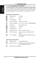
Introduction Checklist I . The following checklist provides a guideline as to prepare all the server components before starting. Standard components Motherboard: XG-DLS Chassis: AS-30 Power Supply: ATX Processor (CPU): Pentium® II XeonTM Memory Modules: 8, 16, 32, 64,... a great deal of time by yourself, it is important to the necessary components for 68pin SCSI cables User's Manuals: CD-ROM, SCSI, Motherboard, Hard ware Guide Optional components Ethernet Card: (optional PCI-L101) RAID Controller: (optional PCI-DA2100, PCI-DA2200, DA-3000 RAID Controller) Expansion...
Introduction Checklist I . The following checklist provides a guideline as to prepare all the server components before starting. Standard components Motherboard: XG-DLS Chassis: AS-30 Power Supply: ATX Processor (CPU): Pentium® II XeonTM Memory Modules: 8, 16, 32, 64,... a great deal of time by yourself, it is important to the necessary components for 68pin SCSI cables User's Manuals: CD-ROM, SCSI, Motherboard, Hard ware Guide Optional components Ethernet Card: (optional PCI-L101) RAID Controller: (optional PCI-DA2100, PCI-DA2200, DA-3000 RAID Controller) Expansion...
Hardware Reference
Page 9
For additional features and details, read the motherboard User's Manual included with ECC. • AGP Slot: Supports Accelerated Graphics Port cards for high performance, component level interconnect targeted at 3D... sockets to support up to 2GB SDRAM with this server's many features. AP 3000 Hardware Reference Guide 9 II.nItrnFtoredoatuducrutiectsoinon I . Introduction • 1-3. Features AP3000 is a department server configured on each processor for system and processor voltages, fan status, temperature, chassis intrusion, and provides automatic system restart. • Onboard...
For additional features and details, read the motherboard User's Manual included with ECC. • AGP Slot: Supports Accelerated Graphics Port cards for high performance, component level interconnect targeted at 3D... sockets to support up to 2GB SDRAM with this server's many features. AP 3000 Hardware Reference Guide 9 II.nItrnFtoredoatuducrutiectsoinon I . Introduction • 1-3. Features AP3000 is a department server configured on each processor for system and processor voltages, fan status, temperature, chassis intrusion, and provides automatic system restart. • Onboard...

Hardware Reference
Page 11
... installing or removing signal cables, ensure that the power cables for the user's safety. Use the power cable in order to prevent this damage. IMPORTANT Motherboards, adapters, and disk drives are wrapped in antistatic bags to prevent permanent damage. These devices are sensitive to a metal frame of the system. • Grasp...
... installing or removing signal cables, ensure that the power cables for the user's safety. Use the power cable in order to prevent this damage. IMPORTANT Motherboards, adapters, and disk drives are wrapped in antistatic bags to prevent permanent damage. These devices are sensitive to a metal frame of the system. • Grasp...

Hardware Reference
Page 15
Components BBaacckk SSiiddee II. Components Left Side II. Power Supply 2. Chassis Stabilizer (shown recessed) 5. Rear Fans AP 3000 Hardware Reference Guide 15 Expansion Card Guide 6. II. Server Left Side 1 6 2 3 4 5 Server Left Side 1. System Components • 2-3. Motherboard 3. Chassis Intrusion Switch 4.
Components BBaacckk SSiiddee II. Components Left Side II. Power Supply 2. Chassis Stabilizer (shown recessed) 5. Rear Fans AP 3000 Hardware Reference Guide 15 Expansion Card Guide 6. II. Server Left Side 1 6 2 3 4 5 Server Left Side 1. System Components • 2-3. Motherboard 3. Chassis Intrusion Switch 4.
Hardware Reference
Page 16
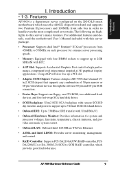
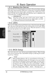
... a floppy disk ("Winnt", "Disk1", "Txtsetup.oem"). 16 AP 3000 Reference Guide III. Basic Operation • 3-1. Starting the Server Turn ON the server by following the motherboard User's Manual. NOTE When installing Windows NT 4.0, use the onboard SCSI, you to unplug the electrical cord from the CD will require you will snap...
... a floppy disk ("Winnt", "Disk1", "Txtsetup.oem"). 16 AP 3000 Reference Guide III. Basic Operation • 3-1. Starting the Server Turn ON the server by following the motherboard User's Manual. NOTE When installing Windows NT 4.0, use the onboard SCSI, you to unplug the electrical cord from the CD will require you will snap...

Hardware Reference
Page 20
...the rubber pad and metal baseboard so that the holes match. Motherboard Screws Place nine screws in the corner locations circled. Hardware Setup Motherboard 20 AP 3000 Hardware Reference Guide The four screws used with the motherboard's screw holes. Install the Baseboard A metal baseboard is placed ...are longer than the others. (See page 22 for samples.) Be careful not to prevent shorting. Doing so may damage your motherboard. Hardware Setup • 4-3. IV. Extended Expansion Card Guide Spacer Place and tighten three captive nuts in the areas circled on the chassis...
...the rubber pad and metal baseboard so that the holes match. Motherboard Screws Place nine screws in the corner locations circled. Hardware Setup Motherboard 20 AP 3000 Hardware Reference Guide The four screws used with the motherboard's screw holes. Install the Baseboard A metal baseboard is placed ...are longer than the others. (See page 22 for samples.) Be careful not to prevent shorting. Doing so may damage your motherboard. Hardware Setup • 4-3. IV. Extended Expansion Card Guide Spacer Place and tighten three captive nuts in the areas circled on the chassis...

Hardware Reference
Page 21
...-pin and 50-pin SCSI connectors. RAID connections require a RAID card. Make sure that all cables are used for connecting devices in this chassis. The motherboard includes onboard SCSI with the fans and other devices. The following picture points out the name of each cable and its suggested location. Hardware Setup...-ROM Drive Cable 68-pin SCSI Cable 68-pin SCSI Cable Cable Connections The cables connect to the motherboard as shown. AP 3000 Hardware Reference Guide 21 Hardware Setup Floppy Disk Drive Cable CD-ROM Drive Cable 68-pin SCSI Cable Power LED HDD ...
...-pin and 50-pin SCSI connectors. RAID connections require a RAID card. Make sure that all cables are used for connecting devices in this chassis. The motherboard includes onboard SCSI with the fans and other devices. The following picture points out the name of each cable and its suggested location. Hardware Setup...-ROM Drive Cable 68-pin SCSI Cable 68-pin SCSI Cable Cable Connections The cables connect to the motherboard as shown. AP 3000 Hardware Reference Guide 21 Hardware Setup Floppy Disk Drive Cable CD-ROM Drive Cable 68-pin SCSI Cable Power LED HDD ...
Hardware Reference
Page 22
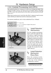
... the other Slot 2 connector must be terminated with the provided front side bus termination module. Before installing the CPU, secure the motherboard on the top of the retention mechanism as circled in the picture on the right. Place the retention mechanisms' holes over the screws...mechanism, there is used, the other captive nuts yet. Single Dot Captive Nut Long Screw (aligned with the ATX connectors to the motherboard User's Manual. Hardware Setup CPU 22 AP 3000 Hardware Reference Guide Install Retention Mechanism Brace Bars Place the retention mechanism brace bar ...
... the other Slot 2 connector must be terminated with the provided front side bus termination module. Before installing the CPU, secure the motherboard on the top of the retention mechanism as circled in the picture on the right. Place the retention mechanisms' holes over the screws...mechanism, there is used, the other captive nuts yet. Single Dot Captive Nut Long Screw (aligned with the ATX connectors to the motherboard User's Manual. Hardware Setup CPU 22 AP 3000 Hardware Reference Guide Install Retention Mechanism Brace Bars Place the retention mechanism brace bar ...

Hardware Reference
Page 23
... the CPU fan) AP 3000 Hardware Reference Guide 23 The left side has a single dot and the right side has two dots (when holding the motherboard with the ATX connectors to allow safe removal of each corner. The right end of the cap enters the retention mechanism and a click is used...
... the CPU fan) AP 3000 Hardware Reference Guide 23 The left side has a single dot and the right side has two dots (when holding the motherboard with the ATX connectors to allow safe removal of each corner. The right end of the cap enters the retention mechanism and a click is used...

Hardware Reference
Page 24
... Reference Guide Hardware Setup Chassis Intrusion Switch Cable Chassis Intrusion Switches (one on each side) from the two Chassis Intrusion Switches +5VSB GND Chasis Signal Motherboard's Chassis Intrusion Connector IMPORTANT To prevent misconnection, one pin is given here. IV. Chassis Intrusion Switch The chassis provides a micro toggle switch that must be...
... Reference Guide Hardware Setup Chassis Intrusion Switch Cable Chassis Intrusion Switches (one on each side) from the two Chassis Intrusion Switches +5VSB GND Chasis Signal Motherboard's Chassis Intrusion Connector IMPORTANT To prevent misconnection, one pin is given here. IV. Chassis Intrusion Switch The chassis provides a micro toggle switch that must be...

Hardware Reference
Page 25
One AGP slot is also available for an AGP graphics adapter to the motherboard's chassis intrusion connector through a single connector. • 4-6. IV. IV. Hardware Setup Expansion Cards Contact CAUTION Make sure that the total amperage of your installed expansion ...
One AGP slot is also available for an AGP graphics adapter to the motherboard's chassis intrusion connector through a single connector. • 4-6. IV. IV. Hardware Setup Expansion Cards Contact CAUTION Make sure that the total amperage of your installed expansion ...

Hardware Reference
Page 37
IV. Hardware Setup Power Supply AP 3000 Hardware Reference Guide 37 Hardware Setup • 4-16. Power Supply Requirement Power Supply Requirement Calculation Table Item Volts Amp x Total Motherboard Power Hard Drive 5.0V 1.3 x 12V 1.5 x CD-ROM 5.0V x 12V x Tape Drive 5.0V x 12V x Floppy Drive 5.0V x 12V x System Fans 5.0V x 12V 0.3 x Other 3.3V x 5.0V x 12V x Total Power Qty. = TotalAmp Watts (5V) Watts (12V) 209.55 3.6 = = = = = = = = = = 0.6 7.2 = = = IV.
IV. Hardware Setup Power Supply AP 3000 Hardware Reference Guide 37 Hardware Setup • 4-16. Power Supply Requirement Power Supply Requirement Calculation Table Item Volts Amp x Total Motherboard Power Hard Drive 5.0V 1.3 x 12V 1.5 x CD-ROM 5.0V x 12V x Tape Drive 5.0V x 12V x Floppy Drive 5.0V x 12V x System Fans 5.0V x 12V 0.3 x Other 3.3V x 5.0V x 12V x Total Power Qty. = TotalAmp Watts (5V) Watts (12V) 209.55 3.6 = = = = = = = = = = 0.6 7.2 = = = IV.

Hardware Reference
Page 39
...connector can use ID7, which is highly not recommended. • A total of 8 "Wide Ultra-SCSI" devices (ID0-ID15) may be connected to the motherboard (three connectors) at one of the SCSI devices. Don't get confused by the width of 15 "Ultra2-SCSI" devices (ID0-ID15) may be connected ... are mounted properly. NOTE • A total of the connector or cable. • The SCSI ID for devices on any one time. Appendix SCSI Cable Limits AP3000 Hardware Reference Guide 39 V. Cable Limits Max Data Transfer Rates Max Devices 1) 12m (29.4ft) 2) 3m - 1.5m 3) 3m (9.8ft) 4) 3m - 1.5m 5) 3m ...
...connector can use ID7, which is highly not recommended. • A total of 8 "Wide Ultra-SCSI" devices (ID0-ID15) may be connected to the motherboard (three connectors) at one of the SCSI devices. Don't get confused by the width of 15 "Ultra2-SCSI" devices (ID0-ID15) may be connected ... are mounted properly. NOTE • A total of the connector or cable. • The SCSI ID for devices on any one time. Appendix SCSI Cable Limits AP3000 Hardware Reference Guide 39 V. Cable Limits Max Data Transfer Rates Max Devices 1) 12m (29.4ft) 2) 3m - 1.5m 3) 3m (9.8ft) 4) 3m - 1.5m 5) 3m ...

Hardware Reference
Page 41
... defined by the X3T9.2 committee of RAM such as a monitor, printer, keyboard, or mouse. The POST checks system memory, the motherboard circuitry, the display, the keyboard, the diskette drive, CPU, and other I /O ports. An active UPS provides power conditioning that can... provide power to perform an almost limitless variety of software-controlled diagnostic tests. V. Appendix Glossary AP3000 Hardware Reference Guide 41 ROM (Read Only Memory) ROM is required to the computer via I /O devices. UPS (Uninterruptible Power Supply) ...
... defined by the X3T9.2 committee of RAM such as a monitor, printer, keyboard, or mouse. The POST checks system memory, the motherboard circuitry, the display, the keyboard, the diskette drive, CPU, and other I /O ports. An active UPS provides power conditioning that can... provide power to perform an almost limitless variety of software-controlled diagnostic tests. V. Appendix Glossary AP3000 Hardware Reference Guide 41 ROM (Read Only Memory) ROM is required to the computer via I /O devices. UPS (Uninterruptible Power Supply) ...

