Hardware Reference
Page 2
...© 1999 ASUSTeK COMPUTER INC. For previous or updated manuals, BIOS, drivers, or product release information, contact ASUS at http://www.asus.com.tw or through any means, except documentation kept by ASUS; ASUS ASSUMES NO RESPONSIBILITY OR LIABILITY FOR ANY ERRORS OR INACCURACIES THAT MAY APPEAR ... digit before and after the period of the manual revision number. Product Name: AP3000 Manual Revision: 1.00 E321 Release Date: February 1999 2 AP 3000 Hardware Reference Guide IN NO EVENT SHALL ASUS, ITS DIRECTORS, OFFICERS, EMPLOYEES OR AGENTS BE LIABLE FOR ANY INDIRECT, SPECIAL,...
...© 1999 ASUSTeK COMPUTER INC. For previous or updated manuals, BIOS, drivers, or product release information, contact ASUS at http://www.asus.com.tw or through any means, except documentation kept by ASUS; ASUS ASSUMES NO RESPONSIBILITY OR LIABILITY FOR ANY ERRORS OR INACCURACIES THAT MAY APPEAR ... digit before and after the period of the manual revision number. Product Name: AP3000 Manual Revision: 1.00 E321 Release Date: February 1999 2 AP 3000 Hardware Reference Guide IN NO EVENT SHALL ASUS, ITS DIRECTORS, OFFICERS, EMPLOYEES OR AGENTS BE LIABLE FOR ANY INDIRECT, SPECIAL,...
Hardware Reference
Page 7
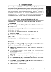
... few symbols used in this server. II. IMPORTANT: Information that MUST be individually purchased to complete the server. PHILIP (CROSS) SCREW DRIVER: Tools required to complete a task. STEP: Actions to complete a task. IntnrtSroeodctiduocutncitsioonn I .II. This guide is intended for this .... IV. NOTE: Tips and information to install or remove the components in completing a task. Introduction You are reading the AP3000 Hardware Reference Guide. WARNING: Information to prevent injury to yourself when trying to help plan your separately purchased components. •...
... few symbols used in this server. II. IMPORTANT: Information that MUST be individually purchased to complete the server. PHILIP (CROSS) SCREW DRIVER: Tools required to complete a task. STEP: Actions to complete a task. IntnrtSroeodctiduocutncitsioonn I .II. This guide is intended for this .... IV. NOTE: Tips and information to install or remove the components in completing a task. Introduction You are reading the AP3000 Hardware Reference Guide. WARNING: Information to prevent injury to yourself when trying to help plan your separately purchased components. •...
Hardware Reference
Page 16
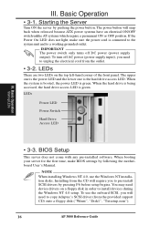
... pushing the power button. IMPORTANT The power switch only turns off AC power (power supply input), you will need device drivers on the top left-hand corner of the front panel. When the system is booted, the power LED is the hard drive access LED. NOTE ...When installing Windows NT 4.0, use the onboard SCSI, you need to copy Adaptec's SCSI driver (from the CD will snap back when released because ATX power systems have an electrical ON/OFF switch unlike AT systems which require a permanent ON...
... pushing the power button. IMPORTANT The power switch only turns off AC power (power supply input), you will need device drivers on the top left-hand corner of the front panel. When the system is booted, the power LED is the hard drive access LED. NOTE ...When installing Windows NT 4.0, use the onboard SCSI, you need to copy Adaptec's SCSI driver (from the CD will snap back when released because ATX power systems have an electrical ON/OFF switch unlike AT systems which require a permanent ON...
Hardware Reference
Page 17
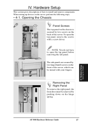
... Setup This section gives descriptions of the server. Removing the Right Panel To remove the right panel, the front door must be turned with a screw driver. NOTE: You do not have to install and remove components.
... Setup This section gives descriptions of the server. Removing the Right Panel To remove the right panel, the front door must be turned with a screw driver. NOTE: You do not have to install and remove components.

Hardware Reference
Page 27
.... Hardware Setup Fixed Storage Devices Fixed Device Bay Cover After releasing the device bay cover clips, pry the cover away from the chassis using a screw driver from the front. Floppy Drive Spacer Fixed Device Spacer AP 3000 Hardware Reference Guide 27 Press these clips in with a screwdriver to cover the CDROM...
.... Hardware Setup Fixed Storage Devices Fixed Device Bay Cover After releasing the device bay cover clips, pry the cover away from the chassis using a screw driver from the front. Floppy Drive Spacer Fixed Device Spacer AP 3000 Hardware Reference Guide 27 Press these clips in with a screwdriver to cover the CDROM...
Hardware Reference
Page 30
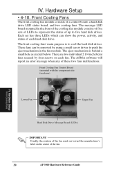
... with the component side facedown) ß,§, Lower Fan Upper Fan IV. IV. There are two individual 2 1/4 inch (6cm) fans secured by using a small screw driver to push the eject mechanism in the front of the cooling fan module consists of five sets of LEDs to represent the status of up...
... with the component side facedown) ß,§, Lower Fan Upper Fan IV. IV. There are two individual 2 1/4 inch (6cm) fans secured by using a small screw driver to push the eject mechanism in the front of the cooling fan module consists of five sets of LEDs to represent the status of up...