

Hardware Reference
Page 5
...37 Output Voltage Regulation, Ripple, and Noise 37 Regulatory Information 37 Safety 37 EMI 37 Glossary 38 Power Supply Requirement Calculation Table 39 AP2500 Hardware Reference Guide 5 Contents SCSI Board Power Installation 24 SCSI ID Setting 25 SCSI ID Dip Switches 27 SCSI Information 27 SCSI Connections... 27 SCSI Termination 27 SCSI ID Jumpers 27 SCSI ID Priority 27 Motherboard Securing 28 Device Cables 29 Cable Connections 29 Card-Secure Module 30 Floppy Disk Drive (1.44MB 31 IDE Cabling 31 CD-ROM Disk...
...37 Output Voltage Regulation, Ripple, and Noise 37 Regulatory Information 37 Safety 37 EMI 37 Glossary 38 Power Supply Requirement Calculation Table 39 AP2500 Hardware Reference Guide 5 Contents SCSI Board Power Installation 24 SCSI ID Setting 25 SCSI ID Dip Switches 27 SCSI Information 27 SCSI Connections... 27 SCSI Termination 27 SCSI ID Jumpers 27 SCSI ID Priority 27 Motherboard Securing 28 Device Cables 29 Cable Connections 29 Card-Secure Module 30 Floppy Disk Drive (1.44MB 31 IDE Cabling 31 CD-ROM Disk...
Hardware Reference
Page 8
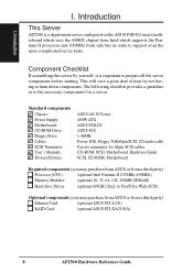
... uses the 440BX chipset from a third party) Ethernet Card: (optional ASUS PCI-L101) RAID Card: (optional ASUS PCI-DA2100A) 8 AP2500 Hardware Reference Guide This will save a great deal of time by yourself, it is a department server configured on the ASUS P2B-D2 smart motherboard which supports the Pentium II processor and 100MHz front side bus...
... uses the 440BX chipset from a third party) Ethernet Card: (optional ASUS PCI-L101) RAID Card: (optional ASUS PCI-DA2100A) 8 AP2500 Hardware Reference Guide This will save a great deal of time by yourself, it is a department server configured on the ASUS P2B-D2 smart motherboard which supports the Pentium II processor and 100MHz front side bus...
Hardware Reference
Page 9
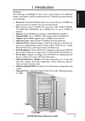
Introduction Features The following are highlights to 2 MB. AP2500 Hardware Reference Guide 9 I . Introduction I . For additional features and details, read the motherboard User's Manual included with three onboard con- nectors to independently connect 68-pin Ultra2 SCSI devices, 68-pin Wide-SCSI devices, and 50-pin Narrow-...
Introduction Features The following are highlights to 2 MB. AP2500 Hardware Reference Guide 9 I . Introduction I . For additional features and details, read the motherboard User's Manual included with three onboard con- nectors to independently connect 68-pin Ultra2 SCSI devices, 68-pin Wide-SCSI devices, and 50-pin Narrow-...

Hardware Reference
Page 10
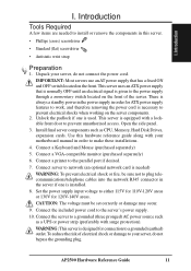
...wired could place hazardous voltage on the antistatic bag. When adding or removing any time you are sensitive to prevent permanent damage. 10 AP2500 Hardware Reference Guide Use one hand, when possible, to connect or disconnect signal cables to prevent this damage. Use the power cable.... Hold drives by the edges. Avoid touching the solder joints or pins. • If you add a device. Static-Sensitive Devices CAUTION: Motherboards, adapters, and disk drives are connecting or disconnecting devices to the workstation. It is out of the antistatic bag, lay it is the responsibility...
...wired could place hazardous voltage on the antistatic bag. When adding or removing any time you are sensitive to prevent permanent damage. 10 AP2500 Hardware Reference Guide Use one hand, when possible, to connect or disconnect signal cables to prevent this damage. Use the power cable.... Hold drives by the edges. Avoid touching the solder joints or pins. • If you add a device. Static-Sensitive Devices CAUTION: Motherboards, adapters, and disk drives are connecting or disconnecting devices to the workstation. It is out of the antistatic bag, lay it is the responsibility...
Hardware Reference
Page 11
...has a fixed ON and OFF switch located on the front of electrical shock or damage to make these installations. 4. I . Unpack your motherboard manual in the server if one is given to prevent unauthorized access. IMPORTANT: Most servers use an AT power supply that is normally OFF... until an electrical signal is used. Open the side panel. 3. AP2500 Hardware Reference Guide 11 Introduction I . There is designed for connection to install or remove the components in order for 120V-140V areas. Connect...
...has a fixed ON and OFF switch located on the front of electrical shock or damage to make these installations. 4. I . Unpack your motherboard manual in the server if one is given to prevent unauthorized access. IMPORTANT: Most servers use an AT power supply that is normally OFF... until an electrical signal is used. Open the side panel. 3. AP2500 Hardware Reference Guide 11 Introduction I . There is designed for connection to install or remove the components in order for 120V-140V areas. Connect...

Hardware Reference
Page 13
...) Server back side Chassis Security To protect the server chassis from unauthorized intrusion, the chassis front panel can be connected to the motherboard's "chassis" connector to show the back exterior components of the chassis side panels' open/close status. System Components Server Back Side... The back side of the server is provided to allow monitoring of this server. AP2500 Hardware Reference Guide 13 Chassis intrusion switches can provide alerting and logging with the built-in keylock. Components II. If either one...
...) Server back side Chassis Security To protect the server chassis from unauthorized intrusion, the chassis front panel can be connected to the motherboard's "chassis" connector to show the back exterior components of the chassis side panels' open/close status. System Components Server Back Side... The back side of the server is provided to allow monitoring of this server. AP2500 Hardware Reference Guide 13 Chassis intrusion switches can provide alerting and logging with the built-in keylock. Components II. If either one...

Hardware Reference
Page 24
System Components SCSI Backplane The SCSI backplane of this bottom SCSI connector. 24 AP2500 Hardware Reference Guide The PWR1 and PWR2 connectors have to be connected to the power supply, the PWR3 connector is comprised of the SCSI board, ... connectors fail to ensure proper orientation of one side with two connectors and three power connectors and another side with the power connector toward the motherboard. SCSI ID Select DIP Switch PWR3 Connector PWR2 Connector PWR1 Connector The provided terminator must be removed. The SCSI board(DA-BP5) dose not has...
System Components SCSI Backplane The SCSI backplane of this bottom SCSI connector. 24 AP2500 Hardware Reference Guide The PWR1 and PWR2 connectors have to be connected to the power supply, the PWR3 connector is comprised of the SCSI board, ... connectors fail to ensure proper orientation of one side with two connectors and three power connectors and another side with the power connector toward the motherboard. SCSI ID Select DIP Switch PWR3 Connector PWR2 Connector PWR1 Connector The provided terminator must be removed. The SCSI board(DA-BP5) dose not has...
Hardware Reference
Page 27
...interfere with onboard SCSI, must have a termination jumper and must disable these termination for instructions. SCSI ID Jumpers All SCSI devices, including this motherboard. SCSI devices vary in a "chain" by jumpers or dip switches. If there are connected together in how they set its termination enabled... ID numbers, 0 through 15. You can support up to 15 SCSI devices to use jumpers, others have a unique address (or SCSI ID). AP2500 Hardware Reference Guide 27 The terminator must set a SCSI ID number (ID 0 to form a "chain." Refer to the manual for any other ...
...interfere with onboard SCSI, must have a termination jumper and must disable these termination for instructions. SCSI ID Jumpers All SCSI devices, including this motherboard. SCSI devices vary in a "chain" by jumpers or dip switches. If there are connected together in how they set its termination enabled... ID numbers, 0 through 15. You can support up to 15 SCSI devices to use jumpers, others have a unique address (or SCSI ID). AP2500 Hardware Reference Guide 27 The terminator must set a SCSI ID number (ID 0 to form a "chain." Refer to the manual for any other ...
Hardware Reference
Page 28
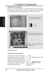
... provides an micro toggle switch that must be connected to the motherboard for the chassis intrusion detection to support all the motherboard expansion cards used in the areas circled on the motherboard. The connection diagram is opened. spacer Place twelve screws in the... are necessary to provide the needed stabilization to work. The motherboard will signal the ASMA software when the side panel is given here. From chassis micro switch Motherboard's chassis intrusion connector Chassis Signal +5VSB 28 AP2500 Hardware Reference Guide Place four spacers in a server. Components...
... provides an micro toggle switch that must be connected to the motherboard for the chassis intrusion detection to support all the motherboard expansion cards used in the areas circled on the motherboard. The connection diagram is opened. spacer Place twelve screws in the... are necessary to provide the needed stabilization to work. The motherboard will signal the ASMA software when the side panel is given here. From chassis micro switch Motherboard's chassis intrusion connector Chassis Signal +5VSB 28 AP2500 Hardware Reference Guide Place four spacers in a server. Components...
Hardware Reference
Page 29
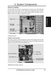
... used for connecting devices in the server. Floppy Cable IDE Cable (CD-ROM) 68-pin WideSCSI Cables (for onboard SCSI Motherboard with cables connected AP2500 Hardware Reference Guide 29 System Fan Module ASUS RAID Card IDE Cable Floppy Cable 68-pin Wide-SCSI for RAID card) Plastic Keeper Cables from contact with 68...
... used for connecting devices in the server. Floppy Cable IDE Cable (CD-ROM) 68-pin WideSCSI Cables (for onboard SCSI Motherboard with cables connected AP2500 Hardware Reference Guide 29 System Fan Module ASUS RAID Card IDE Cable Floppy Cable 68-pin Wide-SCSI for RAID card) Plastic Keeper Cables from contact with 68...
Hardware Reference
Page 31
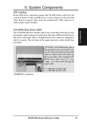
... drive mounts only in case you install an audio card. The only function of IDE hard disk drives. II. The red stripe of power cable AP2500 Hardware Reference Guide 31 CD audio output CD-ROM drive connections NOTE: A CD-ROM audio cable is to direct music CD audio signal to ensure... strength. Components II. Red stripe of signal cable Red stripe of the signal and power cables should face each other. Remove unused cables from the motherboard's IDE connector to your audio card.
... drive mounts only in case you install an audio card. The only function of IDE hard disk drives. II. The red stripe of power cable AP2500 Hardware Reference Guide 31 CD audio output CD-ROM drive connections NOTE: A CD-ROM audio cable is to direct music CD audio signal to ensure... strength. Components II. Red stripe of signal cable Red stripe of the signal and power cables should face each other. Remove unused cables from the motherboard's IDE connector to your audio card.
Hardware Reference
Page 33
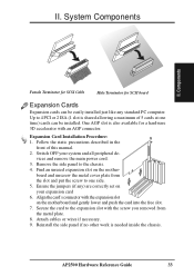
...with the screw you removed from the slot and put the screw to the expansion slot with the expansion slot on the mother- AP2500 Hardware Reference Guide 33 System Components II. One AGP slot is also available for SCSI board Expansion Cards Expansion cards can be easily ...cards can be installed. Follow the static precautions described in the front of 5 cards at one side. 5. Find an unused expansion slot on the motherboard and gently lower and push the card into the free slot. 7. Expansion Card Installation Procedure: 1. Switch OFF your expansion card 6. vices and remove...
...with the screw you removed from the slot and put the screw to the expansion slot with the expansion slot on the mother- AP2500 Hardware Reference Guide 33 System Components II. One AGP slot is also available for SCSI board Expansion Cards Expansion cards can be easily ...cards can be installed. Follow the static precautions described in the front of 5 cards at one side. 5. Find an unused expansion slot on the motherboard and gently lower and push the card into the free slot. 7. Expansion Card Installation Procedure: 1. Switch OFF your expansion card 6. vices and remove...

Hardware Reference
Page 34
... on before opening the side panel. Some products may have auto voltage switching to accommodate 220V-240V or 110-120V but this server's motherboard requirements. The factory default should be done from the inside as shown below. The power supply's main power switch must be turned on your... server for the first time, set manually. Power Supply remove screws 34 AP2500 Hardware Reference Guide It is not. IMPORTANT: For countries using the momentary ATX power switch located on the front panel will occur). Four ...
... on before opening the side panel. Some products may have auto voltage switching to accommodate 220V-240V or 110-120V but this server's motherboard requirements. The factory default should be done from the inside as shown below. The power supply's main power switch must be turned on your... server for the first time, set manually. Power Supply remove screws 34 AP2500 Hardware Reference Guide It is not. IMPORTANT: For countries using the momentary ATX power switch located on the front panel will occur). Four ...

Hardware Reference
Page 36
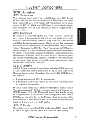
...A total of the devices on any one time. III. Ultra-SCSI technology is unstable over long lenghts, therefore stability will depend on the motherboard. Ultra-SCSI technology is unstable over long lengths, therefore stability will be connected to the 68-pin Wide connector if using a 1.5m (4.... and Wide refers to the Ultra SCSI conditions listed above chart: 1) A total of 15 devices may be connected to the 50-pin Narrow connector. 36 AP2500 Hardware Reference Guide Exceeding the length may be limited to 68 pin. Cable Limits 1) 12m (29.4ft) 2) 3m - 1.5m 3) 3m (9.8ft) ...
...A total of the devices on any one time. III. Ultra-SCSI technology is unstable over long lenghts, therefore stability will depend on the motherboard. Ultra-SCSI technology is unstable over long lengths, therefore stability will be connected to the 68-pin Wide connector if using a 1.5m (4.... and Wide refers to the Ultra SCSI conditions listed above chart: 1) A total of 15 devices may be connected to the 50-pin Narrow connector. 36 AP2500 Hardware Reference Guide Exceeding the length may be limited to 68 pin. Cable Limits 1) 12m (29.4ft) 2) 3m - 1.5m 3) 3m (9.8ft) ...

Hardware Reference
Page 38
III. Appendix Power Supply Requirement Calculation Table Item Volts Amp x Total Motherboard Power Hard Drive 5.0V 1.3 x 12V 1.5 x CD-ROM 5.0V x 12V x Tape Drive 5.0V x 12V x Floppy Drive 5.0V x 12V x System Fans 5.0V x 12V 0.3 x Other 3.3V x 5.0V x 12V x Total Power Qty. = TotalAmp Watts (5V) Watts (12V) 209.55 3.6 = = = = = = = = = = 0.6 7.2 = = = III. Appendix 38 AP2500 Hardware Reference Guide
III. Appendix Power Supply Requirement Calculation Table Item Volts Amp x Total Motherboard Power Hard Drive 5.0V 1.3 x 12V 1.5 x CD-ROM 5.0V x 12V x Tape Drive 5.0V x 12V x Floppy Drive 5.0V x 12V x System Fans 5.0V x 12V 0.3 x Other 3.3V x 5.0V x 12V x Total Power Qty. = TotalAmp Watts (5V) Watts (12V) 209.55 3.6 = = = = = = = = = = 0.6 7.2 = = = III. Appendix 38 AP2500 Hardware Reference Guide
Hardware Reference
Page 40
... of architecture transfers data through the POST, a series of specialized tasks. Peripherals are components on ATX motherboards. The POST checks system memory, the motherboard circuitry, the display, the keyboard, the diskette drive, CPU, and other I /O ports. RAID... (Redundant Array of RAM such as a monitor, printer, keyboard, or mouse. UPS (Uninterruptible Power Supply) A battery system that offers protection against transient power conditions and short-term power outages. 40 AP2500...
... of architecture transfers data through the POST, a series of specialized tasks. Peripherals are components on ATX motherboards. The POST checks system memory, the motherboard circuitry, the display, the keyboard, the diskette drive, CPU, and other I /O ports. RAID... (Redundant Array of RAM such as a monitor, printer, keyboard, or mouse. UPS (Uninterruptible Power Supply) A battery system that offers protection against transient power conditions and short-term power outages. 40 AP2500...

