
Hardware Reference
Page 5
... SCSI Board Power Installation 24 SCSI ID Setting 25 SCSI ID Dip Switches 27 SCSI Information 27 SCSI Connections 27 SCSI Termination 27 SCSI ID Jumpers 27 SCSI ID Priority 27 Motherboard Securing 28 Device Cables 29 Cable Connections 29 Card-Secure Module 30 Floppy Disk Drive (1.44MB 31 IDE Cabling 31 CD-ROM Disk Drive (IDE 31 Ultra2 SCSI Disk Drive 32 External Ultra2 SCSI Terminator 32 Expansion Cards 32 Power Supply 34 Power Supply On and Off 34 Power Supply Mounting 34 Starting the Server 35 III. Appendix 36 SCSI Cable Limits 36 Power Supply...
... SCSI Board Power Installation 24 SCSI ID Setting 25 SCSI ID Dip Switches 27 SCSI Information 27 SCSI Connections 27 SCSI Termination 27 SCSI ID Jumpers 27 SCSI ID Priority 27 Motherboard Securing 28 Device Cables 29 Cable Connections 29 Card-Secure Module 30 Floppy Disk Drive (1.44MB 31 IDE Cabling 31 CD-ROM Disk Drive (IDE 31 Ultra2 SCSI Disk Drive 32 External Ultra2 SCSI Terminator 32 Expansion Cards 32 Power Supply 34 Power Supply On and Off 34 Power Supply Mounting 34 Starting the Server 35 III. Appendix 36 SCSI Cable Limits 36 Power Supply...
Hardware Reference
Page 8
... Chassis: Power Supply: Motherboard: CD-ROM Drive: Floppy Drive: Cables: SCSI Terminator: User's Manuals: Drivers/Utilities: ASUS AS-30 Tower 400W ATX ASUS P2B-D2 ASUS 40X 1.44MB Power, IDE, Floppy, 50&68pin SCSI, CD audio cable Passive terminator for a server. I . This will save a great deal of time by yourself, it is a department server configured on the ASUS P2B-D2 smart motherboard which uses the 440BX chipset from a third party) Ethernet Card: (optional ASUS PCI-L101) RAID Card: (optional ASUS PCI-DA2100A) 8 AP2500 Hardware Reference Guide...
... Chassis: Power Supply: Motherboard: CD-ROM Drive: Floppy Drive: Cables: SCSI Terminator: User's Manuals: Drivers/Utilities: ASUS AS-30 Tower 400W ATX ASUS P2B-D2 ASUS 40X 1.44MB Power, IDE, Floppy, 50&68pin SCSI, CD audio cable Passive terminator for a server. I . This will save a great deal of time by yourself, it is a department server configured on the ASUS P2B-D2 smart motherboard which uses the 440BX chipset from a third party) Ethernet Card: (optional ASUS PCI-L101) RAID Card: (optional ASUS PCI-DA2100A) 8 AP2500 Hardware Reference Guide...
Hardware Reference
Page 9
... system and processor voltages, fan status, temperature, chassis intrusion, and provides automatic system restart. • ASMA and Intel LDSM: Provides server monitoring, management, and control. • Onboard VGA: Onboard S3 TrioV2/DX VGA with three onboard con- nectors to independently connect 68-pin Ultra2 SCSI devices, 68-pin Wide-SCSI devices, and 50-pin Narrow-SCSI devices. • SCSI Backplane: Ultra2 SCSI SCA backplane with remote SCSI ID dip switches and power to support up to...
... system and processor voltages, fan status, temperature, chassis intrusion, and provides automatic system restart. • ASMA and Intel LDSM: Provides server monitoring, management, and control. • Onboard VGA: Onboard S3 TrioV2/DX VGA with three onboard con- nectors to independently connect 68-pin Ultra2 SCSI devices, 68-pin Wide-SCSI devices, and 50-pin Narrow-SCSI devices. • SCSI Backplane: Ultra2 SCSI SCA backplane with remote SCSI ID dip switches and power to support up to...

Hardware Reference
Page 10
... edges. Introduction I . WARNING: An electrical outlet that is out of the antistatic bag, lay it is not correctly wired could place hazardous voltage on the antistatic bag. Before installing or removing signal cables, ensure that the outlet is equipped with a three-wire power cable and plug for those devices are sensitive to prevent this damage. Static-Sensitive Devices CAUTION: Motherboards, adapters, and disk drives...
... edges. Introduction I . WARNING: An electrical outlet that is out of the antistatic bag, lay it is not correctly wired could place hazardous voltage on the antistatic bag. Before installing or removing signal cables, ensure that the outlet is equipped with a three-wire power cable and plug for those devices are sensitive to prevent this damage. Static-Sensitive Devices CAUTION: Motherboards, adapters, and disk drives...
Hardware Reference
Page 11
... CPU, Memory, Hard Disk Drives, expansion cards. Connect the server to the power supply through a momentary switch located on the front of electrical shock or damage to prevent unauthorized access. Unpack your motherboard manual in the server if one is designed for ATX power supply features to work, and therefore removing the power cord is installed. 8. This server uses an ATX power supply that has a fixed ON and OFF switch located on the server components. 2. Set the power supply input voltage to install or remove...
... CPU, Memory, Hard Disk Drives, expansion cards. Connect the server to the power supply through a momentary switch located on the front of electrical shock or damage to prevent unauthorized access. Unpack your motherboard manual in the server if one is designed for ATX power supply features to work, and therefore removing the power cord is installed. 8. This server uses an ATX power supply that has a fixed ON and OFF switch located on the server components. 2. Set the power supply input voltage to install or remove...

Hardware Reference
Page 12
The chassis is made of this server. System Components Server Front Side The front side of the server is powered OFF. 12 AP2500 Hardware Reference Guide Metal Side Access Panel Server front side Power LED ATX Power Button HDD Access LED Floppy Drive CD-ROM Drive Metal Security Door Side Access Panel Screw Metal Door Lock Hot Swap Tray Hard Drive Fan Module Stabilizers WARNING: Always remove the power cord when working on the server internal components to prevent electrical shocks or damage...
The chassis is made of this server. System Components Server Front Side The front side of the server is powered OFF. 12 AP2500 Hardware Reference Guide Metal Side Access Panel Server front side Power LED ATX Power Button HDD Access LED Floppy Drive CD-ROM Drive Metal Security Door Side Access Panel Screw Metal Door Lock Hot Swap Tray Hard Drive Fan Module Stabilizers WARNING: Always remove the power cord when working on the server internal components to prevent electrical shocks or damage...

Hardware Reference
Page 13
... Power In Connector PS/2 Keyboard USB Ports 1 and 2 Serial Port COM1 VGA Connector Top Access Panel Screw Top Access Panel ATX Power Supply PS/2 Mouse Rear Fan Module Parallel Port RJ45 PORT(LAN) Rear Fan Module RAID Controller (Optional) Server back side Chassis Security To protect the server chassis from unauthorized intrusion, the chassis front panel can be connected to the motherboard's "chassis" connector to show the back exterior components of the side panels are opened, the motherboard's onboard hardware monitor can be locked with the provided management software. AP2500...
... Power In Connector PS/2 Keyboard USB Ports 1 and 2 Serial Port COM1 VGA Connector Top Access Panel Screw Top Access Panel ATX Power Supply PS/2 Mouse Rear Fan Module Parallel Port RJ45 PORT(LAN) Rear Fan Module RAID Controller (Optional) Server back side Chassis Security To protect the server chassis from unauthorized intrusion, the chassis front panel can be connected to the motherboard's "chassis" connector to show the back exterior components of the side panels are opened, the motherboard's onboard hardware monitor can be locked with the provided management software. AP2500...

Hardware Reference
Page 14
To open the left view), remove the side panel screw, then pull the handle outward while pulling the panel forward. ATX Power Supply Rear Fan Module SCSI RAID Card (Optional) Server left panel removed, you should see the left side of the server. Each panel is secured by pushing down on each side. To open the right panel, the front door must be removed by two large thumb screws on the front...
To open the left view), remove the side panel screw, then pull the handle outward while pulling the panel forward. ATX Power Supply Rear Fan Module SCSI RAID Card (Optional) Server left panel removed, you should see the left side of the server. Each panel is secured by pushing down on each side. To open the right panel, the front door must be removed by two large thumb screws on the front...
Hardware Reference
Page 15
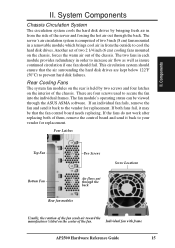
... replacing. The fan module's operating status can be that the air surrounding the hard disk drives are four screws used to secure the fan into the individual frames. If both of them, remove the control board and send it back to the vendor for replacement. Four Latches Top Fan Two Screws Bottom Fan Air flows out through the ASUS ASMA software. If the fans do not work after replacing both fans fail...
... replacing. The fan module's operating status can be that the air surrounding the hard disk drives are four screws used to secure the fan into the individual frames. If both of them, remove the control board and send it back to the vendor for replacement. Four Latches Top Fan Two Screws Bottom Fan Air flows out through the ASUS ASMA software. If the fans do not work after replacing both fans fail...

Hardware Reference
Page 16
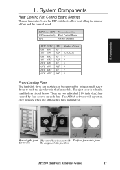
... power when connected to the ASMA software. II. The control board also sends fan status information to the LEDs located on the front of the server and to the control board. II. Components Fan control board with cable connections Rear Cooling Fan Control Board Layout The rear fan control board, although small, has many functions as shown. The fan control board's cable connections are controlled and monitored by a control board. Fan power connector (Reserved Connector) Power input connector Fan status signal connector Fan control settings 16 AP2500 Hardware Reference Guide...
... power when connected to the ASMA software. II. The control board also sends fan status information to the LEDs located on the front of the server and to the control board. II. Components Fan control board with cable connections Rear Cooling Fan Control Board Layout The rear fan control board, although small, has many functions as shown. The fan control board's cable connections are controlled and monitored by a control board. Fan power connector (Reserved Connector) Power input connector Fan status signal connector Fan control settings 16 AP2500 Hardware Reference Guide...
Hardware Reference
Page 17
... software will report an error message when any of Fans 1 2 (Default) 3 4 5 6 7 8 Front Cooling Fans The hard disk drive fan module can be removed by four screws on each fan. Components II. There are two individual 2 1/4 inch (6cm) fans secured by using a small screw driver to allow controlling the number of fans and the control board. Removing the front The control boards mount with The front fan module frame fan module the component side face down AP2500 Hardware Reference Guide 17 DIP Switch SET1 Fan control setting...
... software will report an error message when any of Fans 1 2 (Default) 3 4 5 6 7 8 Front Cooling Fans The hard disk drive fan module can be removed by four screws on each fan. Components II. There are two individual 2 1/4 inch (6cm) fans secured by using a small screw driver to allow controlling the number of fans and the control board. Removing the front The control boards mount with The front fan module frame fan module the component side face down AP2500 Hardware Reference Guide 17 DIP Switch SET1 Fan control setting...

Hardware Reference
Page 18
...) Hard drive Power LED (Green) Hard disk drive message board Message LED Description Power LED off Hard disk drive is to cool the hard disk drives. Gold Finger Connector to the SCSI Back plane Board 3-pin Fan Header pin 1 LED Board Header (For cable to connect to five hard disk drives. The message LED board mounted in rebuilding (*) slow flash Hot-spare hard disk drive (*) on fast flash fast flash Status LED Description off power subsystem OK and ready for operation on Hard disk drive failure (*) fast flash RAID in the front of the cooling fan module consists of five sets of...
...) Hard drive Power LED (Green) Hard disk drive message board Message LED Description Power LED off Hard disk drive is to cool the hard disk drives. Gold Finger Connector to the SCSI Back plane Board 3-pin Fan Header pin 1 LED Board Header (For cable to connect to five hard disk drives. The message LED board mounted in rebuilding (*) slow flash Hot-spare hard disk drive (*) on fast flash fast flash Status LED Description off power subsystem OK and ready for operation on Hard disk drive failure (*) fast flash RAID in the front of the cooling fan module consists of five sets of...

Hardware Reference
Page 19
... chassis using a screw driver from the front. Press these clips in with a screwdriver to release. II. There are provided (as a CD-ROM or tape drive. Fixed storage device tray Fixed Device Bay Cover Clips The device bay panel is held by two plastic clips on removable trays. There are mounted on each side. Removing the device bay cover clips AP2500 Hardware Reference Guide 19 Components II. System Components Fixed Storage Device...
... chassis using a screw driver from the front. Press these clips in with a screwdriver to release. II. There are provided (as a CD-ROM or tape drive. Fixed storage device tray Fixed Device Bay Cover Clips The device bay panel is held by two plastic clips on removable trays. There are mounted on each side. Removing the device bay cover clips AP2500 Hardware Reference Guide 19 Components II. System Components Fixed Storage Device...

Hardware Reference
Page 24
... PWR2 connectors fail to the power supply, the PWR3 connector is comprised of this bottom SCSI connector. 24 AP2500 Hardware Reference Guide The voltage distribution for the three power connectors are six screws on the end connector.(see picture below) SCSI Board Placement There are not equal due to be docked into the server using a SCA connector. SCSI ID Select DIP Switch PWR3 Connector PWR2 Connector PWR1 Connector The provided terminator must be removed. II...
... PWR2 connectors fail to the power supply, the PWR3 connector is comprised of this bottom SCSI connector. 24 AP2500 Hardware Reference Guide The voltage distribution for the three power connectors are six screws on the end connector.(see picture below) SCSI Board Placement There are not equal due to be docked into the server using a SCA connector. SCSI ID Select DIP Switch PWR3 Connector PWR2 Connector PWR1 Connector The provided terminator must be removed. II...
Hardware Reference
Page 27
... set the ID number. Be sure to use by any device you install for instructions. Some use jumpers, others have a unique address (or SCSI ID). AP2500 Hardware Reference Guide 27 Components II. Internal devices connect to the manual for any other SCSI device. External SCSI devices may be connected using a terminator on how to ID 15) for devices in a "chain" by jumpers or dip switches. There are connected together in between the SCSI chain. Refer to the motherboard with...
... set the ID number. Be sure to use by any device you install for instructions. Some use jumpers, others have a unique address (or SCSI ID). AP2500 Hardware Reference Guide 27 Components II. Internal devices connect to the manual for any other SCSI device. External SCSI devices may be connected using a terminator on how to ID 15) for devices in a "chain" by jumpers or dip switches. There are connected together in between the SCSI chain. Refer to the motherboard with...

Hardware Reference
Page 32
... in Ultra2 speeds, a special twisted ribbon cable must use termination jumpers on the device itself. category 5) LAN cabling. II. Components Red stripe of signal cable Red stripe of power cable Ultra2 SCSI hard disk drive connections IMPORTANT: You must be used . 32 AP2500 Hardware Reference Guide Currently Wide-SCSI devices have termination jumpers but Ultra2 devices do not. The signal cable is twisted to wideSCSI ribbon cables (normally colored gray) but usually use Ultra2 SCSI ribbon cables for...
... in Ultra2 speeds, a special twisted ribbon cable must use termination jumpers on the device itself. category 5) LAN cabling. II. Components Red stripe of signal cable Red stripe of power cable Ultra2 SCSI hard disk drive connections IMPORTANT: You must be used . 32 AP2500 Hardware Reference Guide Currently Wide-SCSI devices have termination jumpers but Ultra2 devices do not. The signal cable is twisted to wideSCSI ribbon cables (normally colored gray) but usually use Ultra2 SCSI ribbon cables for...

Hardware Reference
Page 34
... the chassis back side. The factory default should be set the power supply's voltage. Power Supply remove screws 34 AP2500 Hardware Reference Guide System Components Power Supply This server has a standard power supply with specifications to meet this power supply must be turned on before opening the side panel. Some products may have auto voltage switching to visually inspect the switch yourself in case it is not. CAUTION: Before turning on the power supply or chassis. Power Supply Mounting Mounting and unmounting the power supply must...
... the chassis back side. The factory default should be set the power supply's voltage. Power Supply remove screws 34 AP2500 Hardware Reference Guide System Components Power Supply This server has a standard power supply with specifications to meet this power supply must be turned on before opening the side panel. Some products may have auto voltage switching to visually inspect the switch yourself in case it is not. CAUTION: Before turning on the power supply or chassis. Power Supply Mounting Mounting and unmounting the power supply must...
Hardware Reference
Page 35
... your hard disk. Reboot your devices (such as the ASUS PCI-DA2100A and then run the RAID setup program from the BIOS main menu. If the Power On LED does not light, make settings. When booting your server for the first time, hold the "Delete" key and enter BIOS setup in order to install drivers for your server with the server operating system or create your ISA expansion card. Use the boot diskettes provided with the operating system boot disk in order...
... your hard disk. Reboot your devices (such as the ASUS PCI-DA2100A and then run the RAID setup program from the BIOS main menu. If the Power On LED does not light, make settings. When booting your server for the first time, hold the "Delete" key and enter BIOS setup in order to install drivers for your server with the server operating system or create your ISA expansion card. Use the boot diskettes provided with the operating system boot disk in order...
Hardware Reference
Page 39
... widely used to use a different IRQ and address assignment. CHKDSK (Check Disk) An MS-DOS command that defines a 32-bit data bus interface. Currently, there are socket 7, slot 1, and slot 2 CPUs. Each LPT port is a specification that gives you information such as the "brain" of eight contiguous bits. PCI Bus (Peripheral Component Interconnect Local Bus) PCI bus is configured to partition the hard disk drive. Appendix Glossary III. IDE (Integrated Drive Electronics) IDE devices integrate the drive control...
... widely used to use a different IRQ and address assignment. CHKDSK (Check Disk) An MS-DOS command that defines a 32-bit data bus interface. Currently, there are socket 7, slot 1, and slot 2 CPUs. Each LPT port is a specification that gives you information such as the "brain" of eight contiguous bits. PCI Bus (Peripheral Component Interconnect Local Bus) PCI bus is configured to partition the hard disk drive. Appendix Glossary III. IDE (Integrated Drive Electronics) IDE devices integrate the drive control...
Hardware Reference
Page 40
... drives for connecting many peripheral devices. ROM (Read Only Memory) ROM is required to the computer via I /O devices. POST (Power On Self Test) When you turn on ATX motherboards. RAID (Redundant Array of specialized tasks. Flash ROM (or EEPROM) can provide power to perform an almost limitless variety of Inexpensive Disks) RAID can be set up to store permanent programs (called firmware) used on the computer, it will first run through a 16-bit or 32-bit bus...
... drives for connecting many peripheral devices. ROM (Read Only Memory) ROM is required to the computer via I /O devices. POST (Power On Self Test) When you turn on ATX motherboards. RAID (Redundant Array of specialized tasks. Flash ROM (or EEPROM) can provide power to perform an almost limitless variety of Inexpensive Disks) RAID can be set up to store permanent programs (called firmware) used on the computer, it will first run through a 16-bit or 32-bit bus...


