
AP130 User Manual English Edition
Page 2
... the following page. Manual updates are represented by the digit before and after the period of the manual revision number. SPECIFICATIONS AND INFORMATION CONTAINED IN THIS MANUAL ARE FURNISHED FOR INFORMATIONAL USE ONLY, AND ARE SUBJECT TO CHANGE AT ANY TIME WITHOUT NOTICE, AND SHOULD NOT BE CONSTRUED AS A COMMITMENT BY ASUS. Product warranty or service will not be extended...
... the following page. Manual updates are represented by the digit before and after the period of the manual revision number. SPECIFICATIONS AND INFORMATION CONTAINED IN THIS MANUAL ARE FURNISHED FOR INFORMATIONAL USE ONLY, AND ARE SUBJECT TO CHANGE AT ANY TIME WITHOUT NOTICE, AND SHOULD NOT BE CONSTRUED AS A COMMITMENT BY ASUS. Product warranty or service will not be extended...

AP130 User Manual English Edition
Page 3
... 14 1.2 Front Panel Features 15 1.3 Rear Panel Features 16 1.4 Internal Features 17 Chapter 2: Hardware Setup 19 2.1 Remove the Chassis Cover 20 Unlock the side cover 20 Remove the side cover 20 2.2 Motherboard Placement 21 Placement Direction 21 Motherboard Screws 21 2.3 Install a CPU 22 CPU Socket Location 22 CPU Orientation 22 Unlock the CPU Socket 23 Insert the CPU 23 Secure the CPU 23 Install the Fan Heatsink Assembly 24 2.4 Install System Memory 26 DIMM Sockets Location 26 Install a DIMM 26 3
... 14 1.2 Front Panel Features 15 1.3 Rear Panel Features 16 1.4 Internal Features 17 Chapter 2: Hardware Setup 19 2.1 Remove the Chassis Cover 20 Unlock the side cover 20 Remove the side cover 20 2.2 Motherboard Placement 21 Placement Direction 21 Motherboard Screws 21 2.3 Install a CPU 22 CPU Socket Location 22 CPU Orientation 22 Unlock the CPU Socket 23 Insert the CPU 23 Secure the CPU 23 Install the Fan Heatsink Assembly 24 2.4 Install System Memory 26 DIMM Sockets Location 26 Install a DIMM 26 3

AP130 User Manual English Edition
Page 4
Contents 2.5 Install a Hard Disk Drive 27 Remove the HDD/Floppy Cage 27 Install the HDD 28 Connect the Cables 28 2.6 Replace the Cover 29 Re-install the Cover 29 Chapter 3: Powering Up 31 3.1 Getting Started 32 Connect a Monitor 32 Connect the Power Cord 32 Power On 32 Check Power Status 32 Appendix A: Power Supply 33 A.1 General Description 34 A.2 Specifications 35 Input Characteristics 35 Output Characteristics 35 Over-Voltage Protection (OVP 35 Appendix B: Troubleshooting 47 B.1 Simple Fixes 48 4
Contents 2.5 Install a Hard Disk Drive 27 Remove the HDD/Floppy Cage 27 Install the HDD 28 Connect the Cables 28 2.6 Replace the Cover 29 Re-install the Cover 29 Chapter 3: Powering Up 31 3.1 Getting Started 32 Connect a Monitor 32 Connect the Power Cord 32 Power On 32 Check Power Status 32 Appendix A: Power Supply 33 A.1 General Description 34 A.2 Specifications 35 Input Characteristics 35 Output Characteristics 35 Over-Voltage Protection (OVP 35 Appendix B: Troubleshooting 47 B.1 Simple Fixes 48 4

AP130 User Manual English Edition
Page 6
... a particular installation. This class B digital apparatus complies with FCC Rules Part 15. If this equipment. This equipment generates, uses and can be determined by turning the equipment off and on, the user is encouraged to try to assure compliance with the limits for a Class B digital device, pursuant to Part 15 of the monitor to the graphics card is connected. •...
... a particular installation. This class B digital apparatus complies with FCC Rules Part 15. If this equipment. This equipment generates, uses and can be determined by turning the equipment off and on, the user is encouraged to try to assure compliance with the limits for a Class B digital device, pursuant to Part 15 of the monitor to the graphics card is connected. •...

AP130 User Manual English Edition
Page 7
... all power cables from connectors, slots, sockets and circuitry. • Avoid dust, humidity, and temperature extremes. Operation Safety IMPORTANT • Any mechanical operation on a stable surface. 7 Place the server on this server must be conducted by yourself. Use the power cable with a properly grounded electrical outlet to fix it by certified or experienced engineers. • Before operating the server, carefully read all the manuals included...
... all power cables from connectors, slots, sockets and circuitry. • Avoid dust, humidity, and temperature extremes. Operation Safety IMPORTANT • Any mechanical operation on a stable surface. 7 Place the server on this server must be conducted by yourself. Use the power cable with a properly grounded electrical outlet to fix it by certified or experienced engineers. • Before operating the server, carefully read all the manuals included...

AP130 User Manual English Edition
Page 9
ASUS AP130 Pedestal Server 9 This part includes the target audience, chapter description, and conventions used. About This Manual Introduction "About This Manual" introduces the contents of information that are not contained in this document. It also lists other sources of this manual.
ASUS AP130 Pedestal Server 9 This part includes the target audience, chapter description, and conventions used. About This Manual Introduction "About This Manual" introduces the contents of information that are not contained in this document. It also lists other sources of this manual.
AP130 User Manual English Edition
Page 10
... problems before calling customer support. 10 Introduction: About This Manual It lists the possible causes of this part and try to get started with the AP130 server. 6. It also lists other sources of information that came with the AP130 server after you have to this document. Chapter 2: Hardware Setup This chapter lists the hardware setup procedures that you have installed the basic components. 5. Appendix B: Troubleshooting This appendix lists the common problems...
... problems before calling customer support. 10 Introduction: About This Manual It lists the possible causes of this part and try to get started with the AP130 server. 6. It also lists other sources of information that came with the AP130 server after you have to this document. Chapter 2: Hardware Setup This chapter lists the hardware setup procedures that you have installed the basic components. 5. Appendix B: Troubleshooting This appendix lists the common problems...

AP130 User Manual English Edition
Page 11
... the ASUS Contact Information on ASUS hardware and softare products. WARNING: Information to prevent injury to yourself when trying to complete a task. ASUS AP130 Pedestal Server 11 IMPORTANT: Information that you perform certain tasks properly, take note of the standard server package. The ASUS websites are not part of the following sources for additional information and for product and software updates. 1. Conventions...
... the ASUS Contact Information on ASUS hardware and softare products. WARNING: Information to prevent injury to yourself when trying to complete a task. ASUS AP130 Pedestal Server 11 IMPORTANT: Information that you perform certain tasks properly, take note of the standard server package. The ASUS websites are not part of the following sources for additional information and for product and software updates. 1. Conventions...

AP130 User Manual English Edition
Page 12
System Package Contents The following checklist enumerates the components included in the standard system package. 1) ASUS AS11 chassis 2) ASUS P4B-MX motherboard 3) 200W ATX power supply 4) 52X CD-ROM drive 5) 1.44MB floppy disk drive 6) AGP 4X card (optional) 7) Support CD that includes drivers, utilities, and ASUS Server Web-based Management (ASWM) 8) User's manuals (for system and motherboard) If any of the above items is missing, contact your dealer. 12 Introduction: About This Manual
System Package Contents The following checklist enumerates the components included in the standard system package. 1) ASUS AS11 chassis 2) ASUS P4B-MX motherboard 3) 200W ATX power supply 4) 52X CD-ROM drive 5) 1.44MB floppy disk drive 6) AGP 4X card (optional) 7) Support CD that includes drivers, utilities, and ASUS Server Web-based Management (ASWM) 8) User's manuals (for system and motherboard) If any of the above items is missing, contact your dealer. 12 Introduction: About This Manual
AP130 User Manual English Edition
Page 14
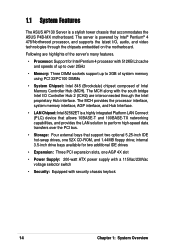
... slot • Power Supply: 200-watt ATX power supply with a 115Vac/230Vac voltage selector switch • Security: Equipped with 512KB L2 cache and speeds of up to over the PCI bus. • Storage: Four external bays that accommodates the ASUS P4B-MX motherboard. The MCH along with the south bridge Intel I /O, audio, and video technologies through the Intel proprietary Hub interface. 1.1 System Features The ASUS AP130 Server is powered...
... slot • Power Supply: 200-watt ATX power supply with a 115Vac/230Vac voltage selector switch • Security: Equipped with 512KB L2 cache and speeds of up to over the PCI bus. • Storage: Four external bays that accommodates the ASUS P4B-MX motherboard. The MCH along with the south bridge Intel I /O, audio, and video technologies through the Intel proprietary Hub interface. 1.1 System Features The ASUS AP130 Server is powered...
AP130 User Manual English Edition
Page 15
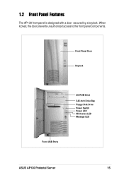
Front Panel Door Keylock CD-ROM Drive 5.25-inch Drive Bay Floppy Disk Drive Power Switch Power LED HD Access LED Message LED Front USB Ports ASUS AP130 Pedestal Server 15 When locked, the door prevents unauthorized access to the front panel components. 1.2 Front Panel Features The AP130 front panel is designed with a door secured by a keylock.
Front Panel Door Keylock CD-ROM Drive 5.25-inch Drive Bay Floppy Disk Drive Power Switch Power LED HD Access LED Message LED Front USB Ports ASUS AP130 Pedestal Server 15 When locked, the door prevents unauthorized access to the front panel components. 1.2 Front Panel Features The AP130 front panel is designed with a door secured by a keylock.

AP130 User Manual English Edition
Page 16
... Use this switch to select the appropriate voltage according to the ports. 1.3 Rear Panel Features The AP130 rear panel includes the external I/O ports. PS/2 KB Serial Line Out Line In Mic USB AC Power PS/2 Mouse Parallel Game/MIDI RJ-45 VGA Voltage Selector The switching power supply that you connect to the voltage supply in your area. The following picture shows the cable connectors and the devices that came with the server has a voltage...
... Use this switch to select the appropriate voltage according to the ports. 1.3 Rear Panel Features The AP130 rear panel includes the external I/O ports. PS/2 KB Serial Line Out Line In Mic USB AC Power PS/2 Mouse Parallel Game/MIDI RJ-45 VGA Voltage Selector The switching power supply that you connect to the voltage supply in your area. The following picture shows the cable connectors and the devices that came with the server has a voltage...

AP130 User Manual English Edition
Page 17
CD-ROM Drive 3. 5.25-inch Drive Bay 4. P4B-MX Motherboard 7. The picture below shows the standard components of the server. 1 2 3 4 5 6 7 1. Power Supply 2. AGP 4X Card (optional) ASUS AP130 Pedestal Server 17 1.4 Internal Features The standard components inside the AP130 server include the motherboard, power supply, floppy and CD-ROM drives, and cables. Floppy Disk Drive 5. 3.5-inch Internal Drive Bays 6.
CD-ROM Drive 3. 5.25-inch Drive Bay 4. P4B-MX Motherboard 7. The picture below shows the standard components of the server. 1 2 3 4 5 6 7 1. Power Supply 2. AGP 4X Card (optional) ASUS AP130 Pedestal Server 17 1.4 Internal Features The standard components inside the AP130 server include the motherboard, power supply, floppy and CD-ROM drives, and cables. Floppy Disk Drive 5. 3.5-inch Internal Drive Bays 6.
AP130 User Manual English Edition
Page 21
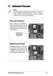
... the motherboard. The edge with the external ports goes to the motherboard user's manual for detailed technical information about the motherboard. Place this side towards the rear of the chassis Motherboard Screws Place eight (8) screws in section "1.4 Internal Features". ASUS AP130 Pedestal Server 21 Refer to the rear part of the chassis. Do not overtighten the screws. 2.2 Motherboard Placement NOTE The motherboard and other internal components of the AP130 server are already installed as...
... the motherboard. The edge with the external ports goes to the motherboard user's manual for detailed technical information about the motherboard. Place this side towards the rear of the chassis Motherboard Screws Place eight (8) screws in section "1.4 Internal Features". ASUS AP130 Pedestal Server 21 Refer to the rear part of the chassis. Do not overtighten the screws. 2.2 Motherboard Placement NOTE The motherboard and other internal components of the AP130 server are already installed as...
AP130 User Manual English Edition
Page 27
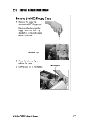
Retaining clip ASUS AP130 Pedestal Server 27 Make sure to release the cage. 3. HDD Metal Cage 2. 2.5 Install a Hard Disk Drive Remove the HDD/Floppy Cage 1. Remove the screw that secures the HDD/floppy cage. Lift the cage out of the chassis. Press the retaining clip to disconnect the floppy cable from the floppy disk before removing the cage out of the chassis.
Retaining clip ASUS AP130 Pedestal Server 27 Make sure to release the cage. 3. HDD Metal Cage 2. 2.5 Install a Hard Disk Drive Remove the HDD/Floppy Cage 1. Remove the screw that secures the HDD/floppy cage. Lift the cage out of the chassis. Press the retaining clip to disconnect the floppy cable from the floppy disk before removing the cage out of the chassis.

AP130 User Manual English Edition
Page 31
Powering up the server basically includes connecting the cables and turning power on. Chapter 3 This chapter tells how to get started with the AP130 server. Powering Up ASUS AP130 Pedestal Server 31
Powering up the server basically includes connecting the cables and turning power on. Chapter 3 This chapter tells how to get started with the AP130 server. Powering Up ASUS AP130 Pedestal Server 31

AP130 User Manual English Edition
Page 32
... system installations in your area. 2. If it doesn't, check the power connection. Power Switch Check Power Status After turning on the front panel. Video Port Connect the Power Cord 1. Connect a Monitor Connect a monitor by pressing the power switch on the power, the power LED lights up the server. Adjust the voltage selector to the correct voltage in Chapter 2, then follow these steps to a grounded wall socket. Power Connector Voltage Selector Power On Turn on the server by plugging hte monitor cable to the power connector on the server rear panel. Connect a power cord...
... system installations in your area. 2. If it doesn't, check the power connection. Power Switch Check Power Status After turning on the front panel. Video Port Connect the Power Cord 1. Connect a Monitor Connect a monitor by pressing the power switch on the power, the power LED lights up the server. Adjust the voltage selector to the correct voltage in Chapter 2, then follow these steps to a grounded wall socket. Power Connector Voltage Selector Power On Turn on the server by plugging hte monitor cable to the power connector on the server rear panel. Connect a power cord...
AP130 User Manual English Edition
Page 33
Power Supply ASUS AP130 Pedestal Server 33 Appendix A This appendix gives information on the 200W switching power supply that comes with the AP130 server.
Power Supply ASUS AP130 Pedestal Server 33 Appendix A This appendix gives information on the 200W switching power supply that comes with the AP130 server.

AP130 User Manual English Edition
Page 38
... DIMMs the system supports. 2. Check the power cable connection on 1. Check the memory modules and make sure that the DIMMs are properly installed on the server and/or the monitor do not light up The keyboard does not work Check the mouse cable if properly connected to a grounded power outlet. 4. Make sure that the system is set to the keyboard port. Problem Action The power LED on the sockets. 38 Appendix B: Troubleshooting Press the power button...
... DIMMs the system supports. 2. Check the power cable connection on 1. Check the memory modules and make sure that the DIMMs are properly installed on the server and/or the monitor do not light up The keyboard does not work Check the mouse cable if properly connected to a grounded power outlet. 4. Make sure that the system is set to the keyboard port. Problem Action The power LED on the sockets. 38 Appendix B: Troubleshooting Press the power button...

AP130 User Manual English Edition
Page 39
... Network connection not available Install the utility drivers from the motherboard support CD. Check the memory modules and make sure you have installed the network drivers from the support CD that came with the package. 1. ASUS AP130 Pedestal Server 39 Make sure that the DIMMs are properly installed on the rear panel. 2. Make sure that you installed the DIMMs the system supports. 2. Make sure the network cable is active. Check if bootable HDD is connector the RJ-45 port...
... Network connection not available Install the utility drivers from the motherboard support CD. Check the memory modules and make sure you have installed the network drivers from the support CD that came with the package. 1. ASUS AP130 Pedestal Server 39 Make sure that the DIMMs are properly installed on the rear panel. 2. Make sure that you installed the DIMMs the system supports. 2. Make sure the network cable is active. Check if bootable HDD is connector the RJ-45 port...


