
Motherboard DIY Troubleshooting Guide
Page 116
...® III Pentium® II Support AP100 1 Slot1 AP200 2 Slot1 AP2000 2 Slot1 AP3000 2 Xeon™ AP2300 2 Socket370 AP6000 2 Slot1 AP8000 2 Xeon™ AP6300 2 Socket370 Maximum Memory (GB) 1 1 1 2 4 1 2 4 Ultra2 SCSI 5.25" Onboard Fixed Storage (Channels) Devices 1 3 1 3 1 4 2 4 2 4 1 4 2 4 2 4 Hot-Swap Trays 0 0 3 or 5* 3 or 5* 3 or 5* 8** 8** 8** * Three 1.6-inch or five 1-inch SCA-2 SCSI hard drives ** Eight...
...® III Pentium® II Support AP100 1 Slot1 AP200 2 Slot1 AP2000 2 Slot1 AP3000 2 Xeon™ AP2300 2 Socket370 AP6000 2 Slot1 AP8000 2 Xeon™ AP6300 2 Socket370 Maximum Memory (GB) 1 1 1 2 4 1 2 4 Ultra2 SCSI 5.25" Onboard Fixed Storage (Channels) Devices 1 3 1 3 1 4 2 4 2 4 1 4 2 4 2 4 Hot-Swap Trays 0 0 3 or 5* 3 or 5* 3 or 5* 8** 8** 8** * Three 1.6-inch or five 1-inch SCA-2 SCSI hard drives ** Eight...

Motherboard DIY Troubleshooting Guide
Page 117
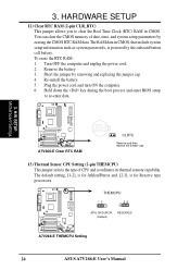
... PCI-DA2200 series support 5x86-133 processor • One 72-pin SIMM socket supports up to 128MB cache memory • Supports three Ultra2 SCSI channels; ASUS AR1000 RAID Sub-system with DA3000 SCSI-to-SCSI RAID Controller • Supports 5x86 RAID processor and two ...capacity • Supports non-RAID, RAID levels 0, 1, 0+1, 3, 5 • On-line failure drive rebuilding • Automatic rebuilding - up to 128MB cache memory • RAID levels 0, 0+1, 3, 5, non-RAID • PCI-DA2200A supports Ultra2 SCSI interface and single channel • PCI-DA2200B supports Ultra2 SCSI interface ...
... PCI-DA2200 series support 5x86-133 processor • One 72-pin SIMM socket supports up to 128MB cache memory • Supports three Ultra2 SCSI channels; ASUS AR1000 RAID Sub-system with DA3000 SCSI-to-SCSI RAID Controller • Supports 5x86 RAID processor and two ...capacity • Supports non-RAID, RAID levels 0, 1, 0+1, 3, 5 • On-line failure drive rebuilding • Automatic rebuilding - up to 128MB cache memory • RAID levels 0, 0+1, 3, 5, non-RAID • PCI-DA2200A supports Ultra2 SCSI interface and single channel • PCI-DA2200B supports Ultra2 SCSI interface ...
A7V266-E User Manual
Page 4
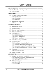
FEATURES 8 2.1 ASUS A7V266-E Motherboard 8 2.1.1 Specifications 8 2.1.2 Performance 10 2.1.3 Intelligence 11 2.2 Motherboard Components 12 2.2.1 Component Locations 13 3. HARDWARE SETUP 14 3.1 Motherboard Layout 14 3.2 Layout Contents 15 3.3 Hardware Setup Procedure 17 3.4 Motherboard Settings 17 3.5 System Memory 25 3.5.1 DDR DIMM Support 25 3.5.1 General DIMM Notes 26 3.5.2 Memory Installation 26 3.6 Central Processing... 4.1.2 Updating BIOS Procedures 47 4.2 BIOS Setup Program 49 4.2.1 BIOS Menu Bar 50 4.2.2 Legend Bar 50 4 ASUS A7V266-E User's Manual CONTENTS 1.
FEATURES 8 2.1 ASUS A7V266-E Motherboard 8 2.1.1 Specifications 8 2.1.2 Performance 10 2.1.3 Intelligence 11 2.2 Motherboard Components 12 2.2.1 Component Locations 13 3. HARDWARE SETUP 14 3.1 Motherboard Layout 14 3.2 Layout Contents 15 3.3 Hardware Setup Procedure 17 3.4 Motherboard Settings 17 3.5 System Memory 25 3.5.1 DDR DIMM Support 25 3.5.1 General DIMM Notes 26 3.5.2 Memory Installation 26 3.6 Central Processing... 4.1.2 Updating BIOS Procedures 47 4.2 BIOS Setup Program 49 4.2.1 BIOS Menu Bar 50 4.2.2 Legend Bar 50 4 ASUS A7V266-E User's Manual CONTENTS 1.

A7V266-E User Manual
Page 8
... identical hard disks to write data to the Infrared Module for a variety of frequency and Vcore voltage through BIOS. 2. FEATURES 2.1 ASUS A7V266-E Motherboard The ASUS A7V266-E motherboard is the perfect answer for RAID levels 0 or 1. DDR DRAM is bundled with advanced features to 100MB/ sec, and ...-100 protocol and Ultra DMA/100 data transfer speeds. The A7V266-E is powered by the AMD® Athlon™/Duron™ processor and is the newest memory standard with EPP and ECP capabilities. UART2 can also be directed from COM2 to each other. 8 ASUS A7V266-E User's Manual
... identical hard disks to write data to the Infrared Module for a variety of frequency and Vcore voltage through BIOS. 2. FEATURES 2.1 ASUS A7V266-E Motherboard The ASUS A7V266-E motherboard is the perfect answer for RAID levels 0 or 1. DDR DRAM is bundled with advanced features to 100MB/ sec, and ...-100 protocol and Ultra DMA/100 data transfer speeds. The A7V266-E is powered by the AMD® Athlon™/Duron™ processor and is the newest memory standard with EPP and ECP capabilities. UART2 can also be directed from COM2 to each other. 8 ASUS A7V266-E User's Manual

A7V266-E User Manual
Page 9
...supports up to 133MB/s maximum throughput.) The MB supports Concurrent PCI, which allows multiple PCI transfers from PCI master bus to the memory and processor. • IDE connectors: Dual-channel bus master IDE connectors support up to support only the latest 1.5 volt AGP ...; PCI Expansion Slots: Provides five 32-bit Legacy Free PCI slots, (PCI 2.2 compliant) with no ISA, eliminating bottlenecks and system memory management issues. ASUS A7V266-E User's Manual 9 FEATURES • Smart BIOS: 2Mb firmware enables Vcore and CPU/DDR SDRAM frequency adjustments, boot block write protection...
...supports up to 133MB/s maximum throughput.) The MB supports Concurrent PCI, which allows multiple PCI transfers from PCI master bus to the memory and processor. • IDE connectors: Dual-channel bus master IDE connectors support up to support only the latest 1.5 volt AGP ...; PCI Expansion Slots: Provides five 32-bit Legacy Free PCI slots, (PCI 2.2 compliant) with no ISA, eliminating bottlenecks and system memory management issues. ASUS A7V266-E User's Manual 9 FEATURES • Smart BIOS: 2Mb firmware enables Vcore and CPU/DDR SDRAM frequency adjustments, boot block write protection...
A7V266-E User Manual
Page 10
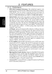
2. This new memory technology increases performance by PC'99. • High-Speed Data Transfer Interface: Support for operating systems that supplies HRTF 3D positional audio functions. Other integrative ... • DDR DRAM Optimized Performance: This motherboard supports a new generation memory, Double Data Rate (DDR) Dynamic Random Access Memory (DDR DRAM). The chip supports software access to the memory and processor. 10 ASUS A7V266-E User's Manual With these features employed in data transfer rates of ASUS smart series motherboards are based on the following high-level...
2. This new memory technology increases performance by PC'99. • High-Speed Data Transfer Interface: Support for operating systems that supplies HRTF 3D positional audio functions. Other integrative ... • DDR DRAM Optimized Performance: This motherboard supports a new generation memory, Double Data Rate (DDR) Dynamic Random Access Memory (DDR DRAM). The chip supports software access to the memory and processor. 10 ASUS A7V266-E User's Manual With these features employed in data transfer rates of ASUS smart series motherboards are based on the following high-level...

A7V266-E User Manual
Page 11
... even in memory on remotely through an internal or external modem. Voltage specifications are monitored to ensure stable voltage to be monitored for future processors, so monitoring is kept in sleep mode. 2. This function reduces both energy consumption and system noise, and is monitored by the ASUS ASIC through the ASUS ASIC. ASUS A7V266-E User...
... even in memory on remotely through an internal or external modem. Voltage specifications are monitored to ensure stable voltage to be monitored for future processors, so monitoring is kept in sleep mode. 2. This function reduces both energy consumption and system noise, and is monitored by the ASUS ASIC through the ASUS ASIC. ASUS A7V266-E User...

A7V266-E User Manual
Page 12
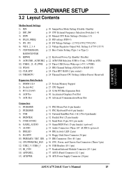
...Athlon™ and Duron™ Processors 2 Feature Setting DIP Switches 3 Chipsets Main Memory VIA® KT266A North Bridge 1 VIA® VT8233 South Bridge 11 Promise IDE / RAID controller 8 ASUS System Monitor controller 9 Multi-I/O controller 20 2Mbit Programmable Flash EEPROM 19 Maximum 3GB ...15 1 ASUS iPanel Audio Connector 16 1 Game/MIDI Port Top) 23 1 Line Out Connector Bottom, left) 23 1 Line In Connector Bottom, center) 23 1 Microphone Connector Bottom, right) 23 Internal Audio Connectors Power ATX Power Supply Connector 5 Form Factor ATX 12 ASUS A7V266-E User...
...Athlon™ and Duron™ Processors 2 Feature Setting DIP Switches 3 Chipsets Main Memory VIA® KT266A North Bridge 1 VIA® VT8233 South Bridge 11 Promise IDE / RAID controller 8 ASUS System Monitor controller 9 Multi-I/O controller 20 2Mbit Programmable Flash EEPROM 19 Maximum 3GB ...15 1 ASUS iPanel Audio Connector 16 1 Game/MIDI Port Top) 23 1 Line Out Connector Bottom, left) 23 1 Line In Connector Bottom, center) 23 1 Microphone Connector Bottom, right) 23 Internal Audio Connectors Power ATX Power Supply Connector 5 Form Factor ATX 12 ASUS A7V266-E User...
A7V266-E User Manual
Page 15
... pin) 13) IR_CON p. 37 Standard Infrared Module Connector (10-1 pin) 14) AFPANEL p. 37 ASUS iPanel Connector (12-1 pin) 15) ATXPWR p. 38 ATX Power Supply Connector (20 pin) ASUS A7V266-E User's Manual 15 HARDWARE SETUP 3.2 Layout Contents Motherboard Settings 1) JEN p. 18 JumperFree Mode Setting ... (Athlon-Duron / Reserved) Expansion Slots/Sockets 1) DIMM 1/2/3 2) Socket 462 3) PCI 1/2/3/4/5 4) AGP Pro 5) ACR Slot p. 25 System Memory Support p. 27 CPU Support p. 28 32-bit PCI Bus Expansion Slots p. 30 Accelerated Graphics Port Slot p. 30 Advanced Communication Riser Slot Connectors...
... pin) 13) IR_CON p. 37 Standard Infrared Module Connector (10-1 pin) 14) AFPANEL p. 37 ASUS iPanel Connector (12-1 pin) 15) ATXPWR p. 38 ATX Power Supply Connector (20 pin) ASUS A7V266-E User's Manual 15 HARDWARE SETUP 3.2 Layout Contents Motherboard Settings 1) JEN p. 18 JumperFree Mode Setting ... (Athlon-Duron / Reserved) Expansion Slots/Sockets 1) DIMM 1/2/3 2) Socket 462 3) PCI 1/2/3/4/5 4) AGP Pro 5) ACR Slot p. 25 System Memory Support p. 27 CPU Support p. 28 32-bit PCI Bus Expansion Slots p. 30 Accelerated Graphics Port Slot p. 30 Advanced Communication Riser Slot Connectors...

A7V266-E User Manual
Page 17
... and expansion cards contain very delicate Integrated Circuit (IC) chips. Install memory modules 3. Whenever you install or remove any component, place the components on your computer: 1. H/W SETUP Motherboard Settings 01 01 01 A7V266-E A7V266-E Onboard LED LED ON Standby Power OFF Powered Off ASUS A7V266-E User's Manual 17 3. HARDWARE SETUP 3.3 Hardware Setup Procedure Complete the...
... and expansion cards contain very delicate Integrated Circuit (IC) chips. Install memory modules 3. Whenever you install or remove any component, place the components on your computer: 1. H/W SETUP Motherboard Settings 01 01 01 A7V266-E A7V266-E Onboard LED LED ON Standby Power OFF Powered Off ASUS A7V266-E User's Manual 17 3. HARDWARE SETUP 3.3 Hardware Setup Procedure Complete the...
A7V266-E User Manual
Page 24
...RAM (2-pin CLR_RTC) This jumper allows you to re-enter data. 01 01 01 01 01 01 3. You can clear the CMOS memory of CPU and coordinates its thermal sensory capability. Hold down the key during the boot process and enter BIOS setup to clear the Real...erasing the CMOS RTC RAM data. Re-install the battery. 5. Plug the power cord and turn ON the computer. 6. A7V266-E THEMCPU 12 23 ATHLON/DURON (Default) RESERVED A7V266-E THEMCPU Setting 24 ASUS A7V266-E User's Manual The default setting, [1-2], is for Athlon/Duron and, [2-3], is powered by the onboard button cell battery....
...RAM (2-pin CLR_RTC) This jumper allows you to re-enter data. 01 01 01 01 01 01 3. You can clear the CMOS memory of CPU and coordinates its thermal sensory capability. Hold down the key during the boot process and enter BIOS setup to clear the Real...erasing the CMOS RTC RAM data. Re-install the battery. 5. Plug the power cord and turn ON the computer. 6. A7V266-E THEMCPU 12 23 ATHLON/DURON (Default) RESERVED A7V266-E THEMCPU Setting 24 ASUS A7V266-E User's Manual The default setting, [1-2], is for Athlon/Duron and, [2-3], is powered by the onboard button cell battery....

A7V266-E User Manual
Page 25
...1GB x1 64MB, 128MB, 256MB, 512MB, 1GB x1 Total System Memory (Max 3GB) = 3. HARDWARE SETUP 3.5 System Memory This motherboard features three Double Data Rate (DDR) Dual Inline Memory Module sockets. 3.5.1 DDR DIMM Support The three DDR DIMM sockets... support 2.5Volt (power level) unbuffered/registered Double Data Rate Synchronous Dynamic Random Access Memory (DDR SDRAM) of the DIMM takes up one row on desktops/laptops). DDR DIMMs support non-ECC memory (used on the motherboard. H/W SETUP System Memory ASUS A7V266...
...1GB x1 64MB, 128MB, 256MB, 512MB, 1GB x1 Total System Memory (Max 3GB) = 3. HARDWARE SETUP 3.5 System Memory This motherboard features three Double Data Rate (DDR) Dual Inline Memory Module sockets. 3.5.1 DDR DIMM Support The three DDR DIMM sockets... support 2.5Volt (power level) unbuffered/registered Double Data Rate Synchronous Dynamic Random Access Memory (DDR SDRAM) of the DIMM takes up one row on desktops/laptops). DDR DIMMs support non-ECC memory (used on the motherboard. H/W SETUP System Memory ASUS A7V266...

A7V266-E User Manual
Page 26
...best performance vs. Because the number of pins are not supported on either side of the breaks, the module will not be possible. 3.5.3 Memory Installation WARNING! 3. double-sided come in the orientation shown. HARDWARE SETUP 3.5.2 General DIMM Notes • DIMMs that have more than 18... chips are different on this motherboard. • ASUS motherboards support SPD (Serial Presence Detect) DIMMs. This is the memory of center. 01 01 01 A7V266-E A7V266-E 184-Pin DDR DIMM Sockets 104 Pins 80 Pins 26 ASUS A7V266-E User's Manual Failure to do so may cause severe damage...
...best performance vs. Because the number of pins are not supported on either side of the breaks, the module will not be possible. 3.5.3 Memory Installation WARNING! 3. double-sided come in the orientation shown. HARDWARE SETUP 3.5.2 General DIMM Notes • DIMMs that have more than 18... chips are different on this motherboard. • ASUS motherboards support SPD (Serial Presence Detect) DIMMs. This is the memory of center. 01 01 01 A7V266-E A7V266-E 184-Pin DDR DIMM Sockets 104 Pins 80 Pins 26 ASUS A7V266-E User's Manual Failure to do so may cause severe damage...

A7V266-E User Manual
Page 27
H/W SETUP System Memory 3. The socket lever must be oriented toward the inner corner of the socket base ... its alignment and look for CPU installation. The heatsink should be fully opened (90 to avoid start-up problems. ASUS A7V266-E User's Manual 27 With the added weight of the CPU must be attached to the CPU to avoid bending the...set the correct Bus Frequency and Multiple (available only on the system. 01 01 01 A7V266-E CPU NOTCH TO INNER CORNER AMD™ CPU LOCK LEVER CPU NOTCH A7V266-E Socket A 1. 3. When mounting a heatsink onto your CPU, make sure that exposed ...
H/W SETUP System Memory 3. The socket lever must be oriented toward the inner corner of the socket base ... its alignment and look for CPU installation. The heatsink should be fully opened (90 to avoid start-up problems. ASUS A7V266-E User's Manual 27 With the added weight of the CPU must be attached to the CPU to avoid bending the...set the correct Bus Frequency and Multiple (available only on the system. 01 01 01 A7V266-E CPU NOTCH TO INNER CORNER AMD™ CPU LOCK LEVER CPU NOTCH A7V266-E Socket A 1. 3. When mounting a heatsink onto your CPU, make sure that exposed ...

A7V266-E User Manual
Page 30
The ACR slot is shipped with ultra-high memory bandwidth. DO NOT remove this label and the safety tab ... shares the same expansion slot with the Audio Modem Riser (AMR) cards. H/W SETUP Expansion Cards A7V266-E A7V266-E Advanced Communication Riser (ACR) 30 ASUS A7V266-E User's Manual The AGP Pro slot is backward compatible with PCI Slot 5. 3. HARDWARE SETUP 3.7.3... notch. Remove the label and tab ONLY if you are using an AGP card without Retention Notch A7V266-E A7V266-E Accelerated Graphics Port (AGP PRO) 20-pin bay Rib (inside slot) TOP VIEW 28-pin bay ...
The ACR slot is shipped with ultra-high memory bandwidth. DO NOT remove this label and the safety tab ... shares the same expansion slot with the Audio Modem Riser (AMR) cards. H/W SETUP Expansion Cards A7V266-E A7V266-E Advanced Communication Riser (ACR) 30 ASUS A7V266-E User's Manual The AGP Pro slot is backward compatible with PCI Slot 5. 3. HARDWARE SETUP 3.7.3... notch. Remove the label and tab ONLY if you are using an AGP card without Retention Notch A7V266-E A7V266-E Accelerated Graphics Port (AGP PRO) 20-pin bay Rib (inside slot) TOP VIEW 28-pin bay ...

A7V266-E User Manual
Page 42
... Audio Connector (10-1 pin AAPANEL) Connect the audio cable from the memory chip of PC/SC smart cards. SMARTCARD A7V266-E 1 A7V266-E Smartcard NC NC SCRREST NC SCRUI SCRRES# VCC NC SCRFET# SCRCLK NC GND NC2 42 ASUS A7V266-E User's Manual 01 01 01 01 01 01 MIC2 AGND Line in_L AGND2 Line in_R ...MICPWR Line out_L AGND3 Line out_R 3. The SmartCard reader permits data access from the optional ASUS iPanel to an optional SmartCard reader device.
... Audio Connector (10-1 pin AAPANEL) Connect the audio cable from the memory chip of PC/SC smart cards. SMARTCARD A7V266-E 1 A7V266-E Smartcard NC NC SCRREST NC SCRUI SCRRES# VCC NC SCRFET# SCRCLK NC GND NC2 42 ASUS A7V266-E User's Manual 01 01 01 01 01 01 MIC2 AGND Line in_L AGND2 Line in_R ...MICPWR Line out_L AGND3 Line out_R 3. The SmartCard reader permits data access from the optional ASUS iPanel to an optional SmartCard reader device.

A7V266-E User Manual
Page 44
... beeps High frequency beeps when system is working Meaning No error during POST No DRAM installed or detected Video card not found or video card memory bad CPU overheated System running , the BIOS beeps or additional messages appear on the screen. If you do not see anything within 30 seconds from... feature,the monitor LED may have failed a power-on tests. For ATX power supplies, you need to an outlet equipped with ATX power supplies. 44 ASUS A7V266-E User's Manual The power supply should turn off (in 4.
... beeps High frequency beeps when system is working Meaning No error during POST No DRAM installed or detected Video card not found or video card memory bad CPU overheated System running , the BIOS beeps or additional messages appear on the screen. If you do not see anything within 30 seconds from... feature,the monitor LED may have failed a power-on tests. For ATX power supplies, you need to an outlet equipped with ATX power supplies. 44 ASUS A7V266-E User's Manual The power supply should turn off (in 4.

A7V266-E User Manual
Page 45
.... 2. Type COPY D:\AFLASH\AFLASH.EXE A:\ (assuming D is a Flash Memory Writer utility that you created. It does not work in DOS mode. AFLASH.EXE is your screen during bootup. Reboot the computer from the hard drive. ASUS A7V266-E User's Manual 45 DO NOT copy AUTOEXEC.BAT and CONFIG.SYS to... create a bootable system disk. This file works only in the DOS prompt within Windows and does not work with a Flash Memory Writer utility (AFLASH.EXE) to reinstall the...
.... 2. Type COPY D:\AFLASH\AFLASH.EXE A:\ (assuming D is a Flash Memory Writer utility that you created. It does not work in DOS mode. AFLASH.EXE is your screen during bootup. Reboot the computer from the hard drive. ASUS A7V266-E User's Manual 45 DO NOT copy AUTOEXEC.BAT and CONFIG.SYS to... create a bootable system disk. This file works only in the DOS prompt within Windows and does not work with a Flash Memory Writer utility (AFLASH.EXE) to reinstall the...

A7V266-E User Manual
Page 48
BIOS SETUP Updating BIOS WARNING! The utility starts to continue. 4. If the Flash Memory Writer utility is updated automatically only when necessary. If this may cause boot problems. Just repeat the process, and if the problem still persists, load ... able to the boot disk. If you encounter problems while updating the new BIOS, DO NOT turn off the system because this happens, call the ASUS service center for support. 48 ASUS A7V266-E User's Manual When the programming is done, Flashed Successfully appears. 8.
BIOS SETUP Updating BIOS WARNING! The utility starts to continue. 4. If the Flash Memory Writer utility is updated automatically only when necessary. If this may cause boot problems. Just repeat the process, and if the problem still persists, load ... able to the boot disk. If you encounter problems while updating the new BIOS, DO NOT turn off the system because this happens, call the ASUS service center for support. 48 ASUS A7V266-E User's Manual When the programming is done, Flashed Successfully appears. 8.

A7V266-E User Manual
Page 57
.... Re-install the battery. 5. Hold down the key during system startup. Halt On [All Errors] This field specifies the types of conventional memory detected by the onboard button cell battery. To confirm the password, type the password again and press . Passwords are ignored. Turn OFF the ...] Installed Memory [XXX MB] This field automatically displays the amount of errors that will cause the system to eight alphanumeric characters. The password is required to enter the BIOS Setup program and to gain full access to the BIOS Setup menus. BIOS SETUP Main Menu ASUS A7V266-E User's...
.... Re-install the battery. 5. Hold down the key during system startup. Halt On [All Errors] This field specifies the types of conventional memory detected by the onboard button cell battery. To confirm the password, type the password again and press . Passwords are ignored. Turn OFF the ...] Installed Memory [XXX MB] This field automatically displays the amount of errors that will cause the system to eight alphanumeric characters. The password is required to enter the BIOS Setup program and to gain full access to the BIOS Setup menus. BIOS SETUP Main Menu ASUS A7V266-E User's...


