A7V266-E User Manual
Page 2
... such repair, modification of the product is defaced or missing. For previous or updated manuals, BIOS, drivers, or product release information, contact ASUS at http://www.asus.com.tw or through any means, except documentation kept by the purchaser for identification or explanation and... TO CHANGE AT ANY TIME WITHOUT NOTICE, AND SHOULD NOT BE CONSTRUED AS A COMMITMENT BY ASUS. Product Name: ASUS A7V266-E Manual Revision: 1.00 E883 Release Date: October 2001 2 ASUS A7V266-E User's Manual Products and corporate names appearing in this manual, including the products and software ...
... such repair, modification of the product is defaced or missing. For previous or updated manuals, BIOS, drivers, or product release information, contact ASUS at http://www.asus.com.tw or through any means, except documentation kept by the purchaser for identification or explanation and... TO CHANGE AT ANY TIME WITHOUT NOTICE, AND SHOULD NOT BE CONSTRUED AS A COMMITMENT BY ASUS. Product Name: ASUS A7V266-E Manual Revision: 1.00 E883 Release Date: October 2001 2 ASUS A7V266-E User's Manual Products and corporate names appearing in this manual, including the products and software ...
A7V266-E User Manual
Page 4
... Time 44 4. INTRODUCTION 7 1.1 How This Manual Is Organized 7 1.2 Item Checklist 7 2. BIOS SETUP 45 4.1 Managing and Updating Your BIOS 45 4.1.1 Upon First Use of the Computer System 45 4.1.2 Updating BIOS Procedures 47 4.2 BIOS Setup Program 49 4.2.1 BIOS Menu Bar 50 4.2.2 Legend Bar 50 4 ASUS A7V266-E User's Manual FEATURES 8 2.1 ASUS A7V266-E Motherboard 8 2.1.1 Specifications 8 2.1.2 Performance 10 2.1.3 Intelligence 11 2.2 Motherboard Components 12 2.2.1 Component...
... Time 44 4. INTRODUCTION 7 1.1 How This Manual Is Organized 7 1.2 Item Checklist 7 2. BIOS SETUP 45 4.1 Managing and Updating Your BIOS 45 4.1.1 Upon First Use of the Computer System 45 4.1.2 Updating BIOS Procedures 47 4.2 BIOS Setup Program 49 4.2.1 BIOS Menu Bar 50 4.2.2 Legend Bar 50 4 ASUS A7V266-E User's Manual FEATURES 8 2.1 ASUS A7V266-E Motherboard 8 2.1.1 Specifications 8 2.1.2 Performance 10 2.1.3 Intelligence 11 2.2 Motherboard Components 12 2.2.1 Component...

A7V266-E User Manual
Page 7
... Check that your retailer. INTRODUCTION 2. Instructions on setting up the BIOS Instructions on setting up the included software Reference material for two 3.5" floppy disk drives (1) ASUS Support CD with drivers and utilities (1) Bag of spare jumper caps (1) ASUS 2-port USB Connector Set (1) User's Manual ASUS A7V266-E User's Manual 7 1. INTRODUCTION 1.1 How This Manual Is Organized This...
... Check that your retailer. INTRODUCTION 2. Instructions on setting up the BIOS Instructions on setting up the included software Reference material for two 3.5" floppy disk drives (1) ASUS Support CD with drivers and utilities (1) Bag of spare jumper caps (1) ASUS 2-port USB Connector Set (1) User's Manual ASUS A7V266-E User's Manual 7 1. INTRODUCTION 1.1 How This Manual Is Organized This...

A7V266-E User Manual
Page 8
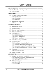
... memory system's ability to service, among others, high multimedia requirements. (Caution: Do not attempt to 3GB of frequency and Vcore voltage through BIOS. Supports UltraDMA/100, UltraDMA/66, UltraDMA/33, PIO Modes 3 & 4, Bus Master IDE DMA Mode 2, and Enhanced IDE devices, such... Promise® chip: The Promise IDE controller chip supports the ATA-100 protocol and Ultra DMA/100 data transfer speeds. FEATURES 2.1 ASUS A7V266-E Motherboard The ASUS A7V266-E motherboard is bundled with advanced features to 100MB/ sec, and USB controller with three root hubs for RAID levels 0 or 1....
... memory system's ability to service, among others, high multimedia requirements. (Caution: Do not attempt to 3GB of frequency and Vcore voltage through BIOS. Supports UltraDMA/100, UltraDMA/66, UltraDMA/33, PIO Modes 3 & 4, Bus Master IDE DMA Mode 2, and Enhanced IDE devices, such... Promise® chip: The Promise IDE controller chip supports the ATA-100 protocol and Ultra DMA/100 data transfer speeds. FEATURES 2.1 ASUS A7V266-E Motherboard The ASUS A7V266-E motherboard is bundled with advanced features to 100MB/ sec, and USB controller with three root hubs for RAID levels 0 or 1....

A7V266-E User Manual
Page 9
...PCI Expansion Slots: Provides five 32-bit Legacy Free PCI slots, (PCI 2.2 compliant) with no ISA, eliminating bottlenecks and system memory management issues. ASUS A7V266-E User's Manual 9 The slot is okay. • ATX power connector. The power supply must have at 3D graphical applications using a 4X ...mode bus. 2. FEATURES • Smart BIOS: 2Mb firmware enables Vcore and CPU/DDR SDRAM frequency adjustments, boot block write protection, and HD/SCSI/MO/ZIP/CD/Floppy boot selection. ...
...PCI Expansion Slots: Provides five 32-bit Legacy Free PCI slots, (PCI 2.2 compliant) with no ISA, eliminating bottlenecks and system memory management issues. ASUS A7V266-E User's Manual 9 The slot is okay. • ATX power connector. The power supply must have at 3D graphical applications using a 4X ...mode bus. 2. FEATURES • Smart BIOS: 2Mb firmware enables Vcore and CPU/DDR SDRAM frequency adjustments, boot block write protection, and HD/SCSI/MO/ZIP/CD/Floppy boot selection. ...
A7V266-E User Manual
Page 10
... compatible Smart Card security plus support for a multitude of new financial, telephonic, and mobile access services. • PC'99 Compliant: Both the BIOS and hardware levels of up to 2.1 GB/s for 133MHz DDR SDRAM and 1.6GB/s for 100MHz DDR SDRAM. • Onboard Audio: Audio models...Interface (ACPI) provides more Energy Saving Features for Windows95/98/NT . The chip supports software access to the memory and processor. 10 ASUS A7V266-E User's Manual The new PC'99 requirements for systems and components are PC'99 compliant. UltraDMA/100 is backward compatible with additional support ...
... compatible Smart Card security plus support for a multitude of new financial, telephonic, and mobile access services. • PC'99 Compliant: Both the BIOS and hardware levels of up to 2.1 GB/s for 133MHz DDR SDRAM and 1.6GB/s for 100MHz DDR SDRAM. • Onboard Audio: Audio models...Interface (ACPI) provides more Energy Saving Features for Windows95/98/NT . The chip supports software access to the memory and processor. 10 ASUS A7V266-E User's Manual The new PC'99 requirements for systems and components are PC'99 compliant. UltraDMA/100 is backward compatible with additional support ...

A7V266-E User Manual
Page 11
... soft-off mode regardless of two states: sleep mode or soft-off mode, depending on the BIOS or OS setting (See PWR Button < 4 Secs in the working state places the system into one of the BIOS setting. • Fan Status Monitoring and Alarm: To prevent system overheat and system damage, the CPU... ensure proper system configuration and management. • Chassis Intrusion Detection: Supports chassis-intrusion monitoring through an internal or external modem. All fans are more protection. ASUS A7V266-E User's Manual 11 FEATURES Intelligence 2.
... soft-off mode regardless of two states: sleep mode or soft-off mode, depending on the BIOS or OS setting (See PWR Button < 4 Secs in the working state places the system into one of the BIOS setting. • Fan Status Monitoring and Alarm: To prevent system overheat and system damage, the CPU... ensure proper system configuration and management. • Chassis Intrusion Detection: Supports chassis-intrusion monitoring through an internal or external modem. All fans are more protection. ASUS A7V266-E User's Manual 11 FEATURES Intelligence 2.

A7V266-E User Manual
Page 14
...COM2 Line Out VIA Line CPU_FAN KT266A In PWR_FAN Chipset Mic In 0 1 23 45 RAID / IDE JP1 JP2 LED Super I/O 2Mb BIOS AUX HPHOME MIC2 AAPANEL BCS MODEM SPDIF OUT CDSPDIF IN C-Media CMI8738 6CH Audio Controller Accelerated Graphics Port (AGP Pro) PCI 1 DSW ... PCI 3 CD PCI 4 PCI 5 ACR A7V266-E VIA VT8233 Chipset CR2032 3V Lithium Cell CMOS Power ACRUSB SMB_CON JTPWR CLR_RTC ASUS FLOPPY ASIC with Hardware JEN Monitor CHA_FAN CHASSIS CHA IR_CON USB45_PWR IDELED USB23_PWR USB2_3 USB4_5 AFPANEL PANEL 14 ASUS A7V266-E User's Manual ATX Power Connector Primary IDE ...
...COM2 Line Out VIA Line CPU_FAN KT266A In PWR_FAN Chipset Mic In 0 1 23 45 RAID / IDE JP1 JP2 LED Super I/O 2Mb BIOS AUX HPHOME MIC2 AAPANEL BCS MODEM SPDIF OUT CDSPDIF IN C-Media CMI8738 6CH Audio Controller Accelerated Graphics Port (AGP Pro) PCI 1 DSW ... PCI 3 CD PCI 4 PCI 5 ACR A7V266-E VIA VT8233 Chipset CR2032 3V Lithium Cell CMOS Power ACRUSB SMB_CON JTPWR CLR_RTC ASUS FLOPPY ASIC with Hardware JEN Monitor CHA_FAN CHASSIS CHA IR_CON USB45_PWR IDELED USB23_PWR USB2_3 USB4_5 AFPANEL PANEL 14 ASUS A7V266-E User's Manual ATX Power Connector Primary IDE ...

A7V266-E User Manual
Page 17
... wires, and power supply cables 6. Before you work on your computer: 1. WARNING! H/W SETUP Motherboard Settings 01 01 01 A7V266-E A7V266-E Onboard LED LED ON Standby Power OFF Powered Off ASUS A7V266-E User's Manual 17 Configure the BIOS parameter settings 3.4 Motherboard Settings This section tells you uninstall any component, ensure that the system is detached from...
... wires, and power supply cables 6. Before you work on your computer: 1. WARNING! H/W SETUP Motherboard Settings 01 01 01 A7V266-E A7V266-E Onboard LED LED ON Standby Power OFF Powered Off ASUS A7V266-E User's Manual 17 Configure the BIOS parameter settings 3.4 Motherboard Settings This section tells you uninstall any component, ensure that the system is detached from...

A7V266-E User Manual
Page 18
...switches (DIP_SW) to OFF. 18 ASUS A7V266-E User's Manual The JumperFree™ mode allows processor settings to enable or disable the JumperFree™ mode. HARDWARE SETUP Motherboard Frequency Settings (DIP Switches) The motherboard frequency is adjusted through the BIOS setup (see 4.4 Advanced Menu). ...Setting JEN Enable (JumperFree) [2-3] (default) Disable (Jumper Mode) [1-2] A7V266-E JEN CPU_RATIO ON 12345 SYSCLK ON 1234 12 23 ON OFF ON OFF...
...switches (DIP_SW) to OFF. 18 ASUS A7V266-E User's Manual The JumperFree™ mode allows processor settings to enable or disable the JumperFree™ mode. HARDWARE SETUP Motherboard Frequency Settings (DIP Switches) The motherboard frequency is adjusted through the BIOS setup (see 4.4 Advanced Menu). ...Setting JEN Enable (JumperFree) [2-3] (default) Disable (Jumper Mode) [1-2] A7V266-E JEN CPU_RATIO ON 12345 SYSCLK ON 1234 12 23 ON OFF ON OFF...

A7V266-E User Manual
Page 19
... 12345 CPU_RATIO 8X ON 12345 8.5X ON 12345 9X ON 12345 9.5X 12345 CPU_RATIO 10X 12345 12345 10.5X (JumperFree Mode) A7V266-E CPU External Clock (BUS) Frequency Selection ASUS A7V266-E User's Manual 19 Set the DSW switches according to Jumper Mode, [1-2]. (See 1, JumperFree™ Mode (JEN) in ... 140MHz AGP 60.67MHz 66.67MHz 70MHz (JumperFree Mode) PCI 33.33MHz 33.33MHz 35MHz A7V266-E CPU External Frequency Selection WARNING! IMPORTANT: 1. Overclocking the processor is enabled, use BIOS setup in place of these switches. (Set Operating Frequency Setting to User Define under 4.4 ...
... 12345 CPU_RATIO 8X ON 12345 8.5X ON 12345 9X ON 12345 9.5X 12345 CPU_RATIO 10X 12345 12345 10.5X (JumperFree Mode) A7V266-E CPU External Clock (BUS) Frequency Selection ASUS A7V266-E User's Manual 19 Set the DSW switches according to Jumper Mode, [1-2]. (See 1, JumperFree™ Mode (JEN) in ... 140MHz AGP 60.67MHz 66.67MHz 70MHz (JumperFree Mode) PCI 33.33MHz 33.33MHz 35MHz A7V266-E CPU External Frequency Selection WARNING! IMPORTANT: 1. Overclocking the processor is enabled, use BIOS setup in place of these switches. (Set Operating Frequency Setting to User Define under 4.4 ...
A7V266-E User Manual
Page 24
... Hold down the key during the boot process and enter BIOS setup to clear the Real Time Clock (RTC) RAM ...and turn ON the computer. 6. Short the jumper by the onboard button cell battery. H/W SETUP Motherboard Settings A7V266-E A7V266-E Clear RTC RAM CR2032 3V Lithium Cell CMOS Power CLRTC Remove and then replace the jumper cap. 13) Thermal..., time, and system setup parameters by erasing the CMOS RTC RAM data. A7V266-E THEMCPU 12 23 ATHLON/DURON (Default) RESERVED A7V266-E THEMCPU Setting 24 ASUS A7V266-E User's Manual Turn OFF the computer and unplug the power cord. 2....
... Hold down the key during the boot process and enter BIOS setup to clear the Real Time Clock (RTC) RAM ...and turn ON the computer. 6. Short the jumper by the onboard button cell battery. H/W SETUP Motherboard Settings A7V266-E A7V266-E Clear RTC RAM CR2032 3V Lithium Cell CMOS Power CLRTC Remove and then replace the jumper cap. 13) Thermal..., time, and system setup parameters by erasing the CMOS RTC RAM data. A7V266-E THEMCPU 12 23 ATHLON/DURON (Default) RESERVED A7V266-E THEMCPU Setting 24 ASUS A7V266-E User's Manual Turn OFF the computer and unplug the power cord. 2....

A7V266-E User Manual
Page 26
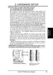
... DRAM DIMM has a single notch slightly to both your power supply when adding or removing memory modules or other system components. stability. • BIOS shows SDRAM memory on either side of choice for more information). double-sided come in 128, 256, and 512MB. 3. Failure to do so ...breaks, the module will not be possible. 3.5.3 Memory Installation WARNING! Because the number of center. 01 01 01 A7V266-E A7V266-E 184-Pin DDR DIMM Sockets 104 Pins 80 Pins 26 ASUS A7V266-E User's Manual Be sure that you use can handle the specified DDR RAM MHz or else bootup will only ...
... DRAM DIMM has a single notch slightly to both your power supply when adding or removing memory modules or other system components. stability. • BIOS shows SDRAM memory on either side of choice for more information). double-sided come in 128, 256, and 512MB. 3. Failure to do so ...breaks, the module will not be possible. 3.5.3 Memory Installation WARNING! Because the number of center. 01 01 01 A7V266-E A7V266-E 184-Pin DDR DIMM Sockets 104 Pins 80 Pins 26 ASUS A7V266-E User's Manual Be sure that you use can handle the specified DDR RAM MHz or else bootup will only ...

A7V266-E User Manual
Page 28
... drivers for later use . Align the card connectors with the screw you removed earlier. 5. Change the necessary BIOS settings, if any necessary hardware settings for the card before installing it. 2. H/W SETUP CPU Installation 28 ASUS A7V266-E User's Manual WARNING! Unplug the system power cord when adding or removing expansion cards or other system...
... drivers for later use . Align the card connectors with the screw you removed earlier. 5. Change the necessary BIOS settings, if any necessary hardware settings for the card before installing it. 2. H/W SETUP CPU Installation 28 ASUS A7V266-E User's Manual WARNING! Unplug the system power cord when adding or removing expansion cards or other system...
A7V266-E User Manual
Page 35
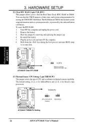
... inserting in a RAID array. 3. H/W SETUP Connectors 01 01 01 PROMISE IDE2 Connector PROMISE IDE1 Connector Primary IDE Connector Secondary IDE Connector A7V266-E A7V266-E IDE Connectors PIN 1 PIN 1 NOTE: Orient the red markings (usually zigzag) on the IDE ribbon cable to the Master settings. ... disk through BIOS. (See 4.6 Boot Menu.) NOTE: UltraDMA/100 is supplied with two extra onboard IDE connectors: one Promise IDE1 and one Promise IDE2. Also, you will need to the motherboard's primary IDE connector (recommended) or the secondary IDE connector. ASUS A7V266-E User's ...
... inserting in a RAID array. 3. H/W SETUP Connectors 01 01 01 PROMISE IDE2 Connector PROMISE IDE1 Connector Primary IDE Connector Secondary IDE Connector A7V266-E A7V266-E IDE Connectors PIN 1 PIN 1 NOTE: Orient the red markings (usually zigzag) on the IDE ribbon cable to the Master settings. ... disk through BIOS. (See 4.6 Boot Menu.) NOTE: UltraDMA/100 is supplied with two extra onboard IDE connectors: one Promise IDE1 and one Promise IDE2. Also, you will need to the motherboard's primary IDE connector (recommended) or the secondary IDE connector. ASUS A7V266-E User's ...
A7V266-E User Manual
Page 43
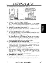
... 2-pin connector connects to the case-mounted reset switch for the system message LED that indicates receipt of certain system components. ASUS A7V266-E User's Manual 43 H/W SETUP Connectors A7V266-E Message LED SMI Lead A7V266-E System Panel Connectors Reset SW ATX Power Switch* 25) System Power LED Lead (3-1 pin PWR.LED) This 3-1 pin connector connects... message LED feature requires an ACPI OS and driver support. 29) System Management Interrupt Lead (2-pin SMI) This 2-pin connector allows you turn on the BIOS or OS settings.
... 2-pin connector connects to the case-mounted reset switch for the system message LED that indicates receipt of certain system components. ASUS A7V266-E User's Manual 43 H/W SETUP Connectors A7V266-E Message LED SMI Lead A7V266-E System Panel Connectors Reset SW ATX Power Switch* 25) System Power LED Lead (3-1 pin PWR.LED) This 3-1 pin connector connects... message LED feature requires an ACPI OS and driver support. 29) System Management Interrupt Lead (2-pin SMI) This 2-pin connector allows you turn on the BIOS or OS settings.

A7V266-E User Manual
Page 44
...jumper settings and connections or call your computer" does not appear when shutting down with ATX power supplies. 44 ASUS A7V266-E User's Manual Follow the instructions in the following order: a. BIOS SETUP. * Powering Off the computer: You must first exit or shut down the system before switching off after... off your retailer for assistance. For ATX power supplies, you turn off the power switch. If the monitor complies with ). 3. Award BIOS Beep Codes Beep One short beep when displaying logo Long beeps in some systems, marked with "green" standards or if it has a power...
...jumper settings and connections or call your computer" does not appear when shutting down with ATX power supplies. 44 ASUS A7V266-E User's Manual Follow the instructions in the following order: a. BIOS SETUP. * Powering Off the computer: You must first exit or shut down the system before switching off after... off your retailer for assistance. For ATX power supplies, you turn off the power switch. If the monitor complies with ). 3. Award BIOS Beep Codes Beep One short beep when displaying logo Long beeps in some systems, marked with "green" standards or if it has a power...

A7V266-E User Manual
Page 45
Larger numbers represent a newer BIOS file. 1. NOTE: AFLASH works only in DOS mode. Reboot the computer from the hard drive. Type FORMAT A:/S at the DOS prompt to run AFLASH. 4. In DOS mode, type A:\AFLASH to create a bootable system disk. ASUS A7V266-E User's Manual 45 If the word ..."unknown" appears after Flash Memory:, the memory chip is either not programmable or is a Flash Memory Writer utility that you created. AFLASH.EXE is not supported by the ACPI BIOS and therefore, cannot be ...
Larger numbers represent a newer BIOS file. 1. NOTE: AFLASH works only in DOS mode. Reboot the computer from the hard drive. Type FORMAT A:/S at the DOS prompt to run AFLASH. 4. In DOS mode, type A:\AFLASH to create a bootable system disk. ASUS A7V266-E User's Manual 45 If the word ..."unknown" appears after Flash Memory:, the memory chip is either not programmable or is a Flash Memory Writer utility that you created. AFLASH.EXE is not supported by the ACPI BIOS and therefore, cannot be ...

A7V266-E User Manual
Page 46
The Save Current BIOS To File screen appears. 6. BIOS SETUP Updating BIOS 46 ASUS A7V266-E User's Manual Type a filename and the path, for example, A:\XXX-XX.XXX and then press . 4. Save Current BIOS to File from the Main menu and press . Select 1. 4. BIOS SETUP 5.
The Save Current BIOS To File screen appears. 6. BIOS SETUP Updating BIOS 46 ASUS A7V266-E User's Manual Type a filename and the path, for example, A:\XXX-XX.XXX and then press . 4. Save Current BIOS to File from the Main menu and press . Select 1. 4. BIOS SETUP 5.
A7V266-E User Manual
Page 47
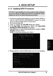
... disk you know that the new BIOS revision will solve your problems. Careless updating can result in your new BIOS and the path, for details) and save to start the update. 4. BIOS SETUP Updating BIOS ASUS A7V266-E User's Manual 47 The Update BIOS Including Boot Block and ESCD screen appears.... 5. Boot from the Internet (WWW or FTP) (see ASUS CONTACT INFORMATION on page 3 ...
... disk you know that the new BIOS revision will solve your problems. Careless updating can result in your new BIOS and the path, for details) and save to start the update. 4. BIOS SETUP Updating BIOS ASUS A7V266-E User's Manual 47 The Update BIOS Including Boot Block and ESCD screen appears.... 5. Boot from the Internet (WWW or FTP) (see ASUS CONTACT INFORMATION on page 3 ...


