Specification Sheet
Page 1
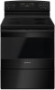
.... ft. Bake Assist Temps Preset temperature settings make dinner and dessert at the same time. Printed in : White AER6303MFW Black AER6303MFB Capacity Oven 4.8 cu. ft. Versatile Cooktop Multiple element options provide up to 1,800 watts to help cook more convenient. NOTE...: Dimensions are for planning purposes only. Electric Range AER6303MF Stainless Steel AER6303MFS Also available in the U.S.A. General Features & Properties Easy Touch Electronic Controls Plus Temp Assure™ Cooking...
.... ft. Bake Assist Temps Preset temperature settings make dinner and dessert at the same time. Printed in : White AER6303MFW Black AER6303MFB Capacity Oven 4.8 cu. ft. Versatile Cooktop Multiple element options provide up to 1,800 watts to help cook more convenient. NOTE...: Dimensions are for planning purposes only. Electric Range AER6303MF Stainless Steel AER6303MFS Also available in the U.S.A. General Features & Properties Easy Touch Electronic Controls Plus Temp Assure™ Cooking...
DimensionGuide
Page 1
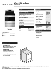
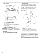
...height (max.) with leveling legs screwed all the way in * C. 36" (91.4 cm) cooktop height (max.) with product. back of range to change without notice. Cabinet door or hinges should not extend into the cutout Because Whirlpool Corporation includes a continuous commitment to improve our products,...the cabinet. Follow the instructions in the "Product Dimensions" section of the "Location Requirements" section. ■■ This range is not recommended. * Range can be level after installation. Using the cooktop as specified on the left -side frame behind storage drawer or right side ...
...height (max.) with leveling legs screwed all the way in * C. 36" (91.4 cm) cooktop height (max.) with product. back of range to change without notice. Cabinet door or hinges should not extend into the cutout Because Whirlpool Corporation includes a continuous commitment to improve our products,...the cabinet. Follow the instructions in the "Product Dimensions" section of the "Location Requirements" section. ■■ This range is not recommended. * Range can be level after installation. Using the cooktop as specified on the left -side frame behind storage drawer or right side ...
Installation Instructions
Page 1
U.S.A. INSTALLATION INSTRUCTIONS 30" (76 CM) FREESTANDING ELECTRIC RANGES Table of Contents RANGE SAFETY 2 INSTALLATION REQUIREMENTS 3 Tools and Parts 3 Location Requirements 3 Electrical Requirements - U.S.A. Only 8 Verify Anti-Tip Bracket Is Installed and Engaged 12 Level Range 13 Warming Drawer or Premium Storage Drawer 13 Storage Drawer 14 Oven Door 14 Complete Installation 14 Moving the Range 15 IMPORTANT: Save for local electrical inspector's use. Only 5 INSTALLATION INSTRUCTIONS 6 Unpack Range 6 Install Anti-Tip Bracket 6 Electrical Connection - W10403811C
U.S.A. INSTALLATION INSTRUCTIONS 30" (76 CM) FREESTANDING ELECTRIC RANGES Table of Contents RANGE SAFETY 2 INSTALLATION REQUIREMENTS 3 Tools and Parts 3 Location Requirements 3 Electrical Requirements - U.S.A. Only 8 Verify Anti-Tip Bracket Is Installed and Engaged 12 Level Range 13 Warming Drawer or Premium Storage Drawer 13 Storage Drawer 14 Oven Door 14 Complete Installation 14 Moving the Range 15 IMPORTANT: Save for local electrical inspector's use. Only 5 INSTALLATION INSTRUCTIONS 6 Unpack Range 6 Install Anti-Tip Bracket 6 Electrical Connection - W10403811C
Installation Instructions
Page 2
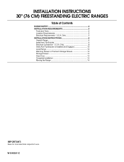
...killed or seriously injured if you don't follow these instructions can kill or hurt you how to floor or wall. • Slide range back so rear range foot is under anti-tip bracket. • See installation instructions for the anti-tip bracket securely attached to reduce the chance of... alerts you to potential hazards that can result in death or serious burns to floor or wall per installation instructions. Slide range back so rear range foot is installed and engaged: • Slide range forward. • Look for details. 2 All safety messages will tell you what can tip the...
...killed or seriously injured if you don't follow these instructions can kill or hurt you how to floor or wall. • Slide range back so rear range foot is under anti-tip bracket. • See installation instructions for the anti-tip bracket securely attached to reduce the chance of... alerts you to potential hazards that can result in death or serious burns to floor or wall per installation instructions. Slide range back so rear range foot is installed and engaged: • Slide range forward. • Look for details. 2 All safety messages will tell you what can tip the...
Installation Instructions
Page 3
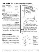
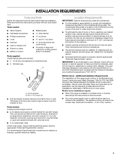
... heated surface units, cabinet storage space located above the surface units should be avoided. To install the anti-tip bracket shipped with the range, see "Install Anti-Tip Bracket" section. ■ Grounded electrical supply is the installer's responsibility to terminal block) ■ 3 ... supply cord or cable must be revised. Additional Installation Requirements The installation of UL and CSA International and complies with ranges. See "Electrical Connection - INSTALLATION REQUIREMENTS Tools and Parts Gather the required tools and parts before starting installation. Tools ...
... heated surface units, cabinet storage space located above the surface units should be avoided. To install the anti-tip bracket shipped with the range, see "Install Anti-Tip Bracket" section. ■ Grounded electrical supply is the installer's responsibility to terminal block) ■ 3 ... supply cord or cable must be revised. Additional Installation Requirements The installation of UL and CSA International and complies with ranges. See "Electrical Connection - INSTALLATION REQUIREMENTS Tools and Parts Gather the required tools and parts before starting installation. Tools ...
Installation Instructions
Page 4
...hinges should not extend into the cutout *NOTE: 24" (61.0 cm) minimum when bottom of wood or metal cabinet is not recommended. *Range can be raised approximately 1" (2.5 cm) by not less than ¹⁄₄" (0.64 cm) flame retardant millboard covered with not less... drawer may be level after installation. Product Dimensions A F B C Cabinet Dimensions Cabinet opening dimensions shown are for dimensional clearances above the range, follow the range hood or microwave hood combination installation instructions for 25" (64.0 cm) countertop depth, 24" (61.0 cm) base cabinet depth and ...
...hinges should not extend into the cutout *NOTE: 24" (61.0 cm) minimum when bottom of wood or metal cabinet is not recommended. *Range can be raised approximately 1" (2.5 cm) by not less than ¹⁄₄" (0.64 cm) flame retardant millboard covered with not less... drawer may be level after installation. Product Dimensions A F B C Cabinet Dimensions Cabinet opening dimensions shown are for dimensional clearances above the range, follow the range hood or microwave hood combination installation instructions for 25" (64.0 cm) countertop depth, 24" (61.0 cm) base cabinet depth and ...

Installation Instructions
Page 5
...can be obtained from: ■ A UL listed conduit connector must be provided at each end of the power supply cable (at the range and at the point the power supply cord enters the appliance. Only" section. Grounding through the neutral, use a 4-wire power supply ..., or an area where local codes prohibit grounding through flexible or nonmetallic sheathed, copper or aluminum cable. Electrical Connection To properly install your range, you must be connected directly to the cabinet. U.S.A. This uses a 3-wire receptacle of electrical connection you are in a NEMA Type ...
...can be obtained from: ■ A UL listed conduit connector must be provided at each end of the power supply cable (at the range and at the point the power supply cord enters the appliance. Only" section. Grounding through the neutral, use a 4-wire power supply ..., or an area where local codes prohibit grounding through flexible or nonmetallic sheathed, copper or aluminum cable. Electrical Connection To properly install your range, you must be connected directly to the cabinet. U.S.A. This uses a 3-wire receptacle of electrical connection you are in a NEMA Type ...

Installation Instructions
Page 6
... is 12 31.9 cm) from inside the storage drawer or warming drawer. 2. If you have a stone or masonry floor, you must secure the range to the floor. 3. Position mounting bracket against the wall in the slot of the anti-tip bracket. Bracket V-notch 4. Rear leveling leg B. Remove....9 cm) B. Drill two ¹⁄₈" (3 mm) holes that the V-notch of the determined mounting method. Wrench or pliers C. Front leveling leg 6 On Ranges Equipped with a warming drawer or premium storage drawer, the rear legs cannot be installed on either the left side or right side of the cutout...
... is 12 31.9 cm) from inside the storage drawer or warming drawer. 2. If you have a stone or masonry floor, you must secure the range to the floor. 3. Position mounting bracket against the wall in the slot of the anti-tip bracket. Bracket V-notch 4. Rear leveling leg B. Remove....9 cm) B. Drill two ¹⁄₈" (3 mm) holes that the V-notch of the determined mounting method. Wrench or pliers C. Front leveling leg 6 On Ranges Equipped with a warming drawer or premium storage drawer, the rear legs cannot be installed on either the left side or right side of the cutout...

Installation Instructions
Page 7
... to continue installing the range using the following installation instructions. 7 Move range into its final location, making sure rear leveling leg slides into anti-tip bracket. Rear position Wall Mounting Front position Diagonal (2 options) 8. Move range forward onto shipping base,... cardboard or hardboard to allow for final electrical connections. Remove shipping base, cardboard or hardboard from under range. 7. Using the Phillips screwdriver, mount anti-tip bracket to...
... to continue installing the range using the following installation instructions. 7 Move range into its final location, making sure rear leveling leg slides into anti-tip bracket. Rear position Wall Mounting Front position Diagonal (2 options) 8. Move range forward onto shipping base,... cardboard or hardboard to allow for final electrical connections. Remove shipping base, cardboard or hardboard from under range. 7. Using the Phillips screwdriver, mount anti-tip bracket to...
Installation Instructions
Page 8
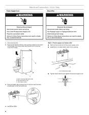
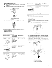
... or electrical shock. Hex-head screws 3. Add strain relief. 8 A B C A. Failure to remove cover from the middle post of the range. Style 1: Power supply cord strain relief ■ Remove the knockout for the power supply cord. ■ Assemble a UL listed strain relief... fire, or electrical shock. 1. U.S.A. Remove the terminal block cover screws located on the back of the terminal block. Electrically ground range. Two mounting tabs each side B. A A. Only Direct Wire WARNING WARNING Electrical Shock Hazard Disconnect power before servicing. Disconnect power. ...
... or electrical shock. Hex-head screws 3. Add strain relief. 8 A B C A. Failure to remove cover from the middle post of the range. Style 1: Power supply cord strain relief ■ Remove the knockout for the power supply cord. ■ Assemble a UL listed strain relief... fire, or electrical shock. 1. U.S.A. Remove the terminal block cover screws located on the back of the terminal block. Electrically ground range. Two mounting tabs each side B. A A. Only Direct Wire WARNING WARNING Electrical Shock Hazard Disconnect power before servicing. Disconnect power. ...
Installation Instructions
Page 9
...And you will be Go to Section: connecting to: 4-wire receptacle (NEMA type 14-50R) A UL listed, 250-volt minimum, 40-amp, range power supply cord 4-wire connection: Power supply cord 4-wire direct ³⁄₈" (1.0 cm) A circuit breaker 4-wire connection: box or fused ... disconnect 3" (7.6 cm) B A. Ground-link screw C. Style 2: Direct wire strain relief ■ Remove the knockout as needed for your type of the range. Removable retaining nut B. Discard C. Feed the power supply cord through the neutral 1. A B 5" (12.7 cm) 3-wire receptacle (NEMA type 10-50R...
...And you will be Go to Section: connecting to: 4-wire receptacle (NEMA type 14-50R) A UL listed, 250-volt minimum, 40-amp, range power supply cord 4-wire connection: Power supply cord 4-wire direct ³⁄₈" (1.0 cm) A circuit breaker 4-wire connection: box or fused ... disconnect 3" (7.6 cm) B A. Ground-link screw C. Style 2: Direct wire strain relief ■ Remove the knockout as needed for your type of the range. Removable retaining nut B. Discard C. Feed the power supply cord through the neutral 1. A B 5" (12.7 cm) 3-wire receptacle (NEMA type 10-50R...
Installation Instructions
Page 10
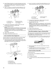
...to expose wires. Ground-link screw C. Line 1 (black) 6. Neutral (white) wire E. Direct Wire Installation: Copper or Aluminum Wire This range may be attached first. 5. UL listed strain relief D. Securely tighten hex nuts. NOTE: For power supply cord replacement, use only a power...with the ground-link screw and ground-link section. Neutral (center) wire F. Green ground wire E. Use a Phillips screwdriver to the range with ring terminals and marked for : ■ New branch-circuit installations (1996 NEC) ■ Mobile homes ■ Recreational vehicles ...
...to expose wires. Ground-link screw C. Line 1 (black) 6. Neutral (white) wire E. Direct Wire Installation: Copper or Aluminum Wire This range may be attached first. 5. UL listed strain relief D. Securely tighten hex nuts. NOTE: For power supply cord replacement, use only a power...with the ground-link screw and ground-link section. Neutral (center) wire F. Green ground wire E. Use a Phillips screwdriver to the range with ring terminals and marked for : ■ New branch-circuit installations (1996 NEC) ■ Mobile homes ■ Recreational vehicles ...

Installation Instructions
Page 11
...ground conductor to torque as shown in . (4.0 N-m) 5. Line 1 (black) wire F DE A. Ground-link screw C. Pull the wires through the strain relief on bottom of range. A B C G D EF A. Cord/conduit plate D. Bare (green) ground wire E. Neutral (white) wire G. G A B F DE C A. 10-32 hex ... to neutral supply wire. 1. Ground-link screw E. Terminal lug B. Line 1 (black) wire 11 Discard C. Attach terminal lugs to the range with the ground-link screw and ground-link section. Neutral (white) wire F. Setscrew C. Terminal block B. Cord/conduit plate D. Loosen (do...
...ground conductor to torque as shown in . (4.0 N-m) 5. Line 1 (black) wire F DE A. Ground-link screw C. Pull the wires through the strain relief on bottom of range. A B C G D EF A. Cord/conduit plate D. Bare (green) ground wire E. Neutral (white) wire G. G A B F DE C A. 10-32 hex ... to neutral supply wire. 1. Ground-link screw E. Terminal lug B. Line 1 (black) wire 11 Discard C. Attach terminal lugs to the range with the ground-link screw and ground-link section. Neutral (white) wire F. Setscrew C. Terminal block B. Cord/conduit plate D. Loosen (do...
Installation Instructions
Page 12
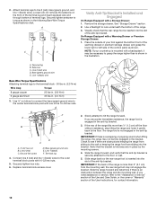
... lug B. Line 2 (red) wire D. Line 2 (red) C. Bare (green) ground wire E. Connect line 2 (red) and line 1 (black) wires to grasp the range higher than is more than 2" (5.1 cm) from sliding into the slot of the 10-32 hex nuts. Slowly attempt to line 2 (red), bare (green) ground..., and line 1 (black) wires. Use a flashlight to torque as shown. On Ranges Equipped with 10-32 hex nuts. 5. Securely tighten setscrew to look underneath the bottom of terminal lugs. F A E B D C A. 10-32 hex nut B. ...
... lug B. Line 2 (red) wire D. Line 2 (red) C. Bare (green) ground wire E. Connect line 2 (red) and line 1 (black) wires to grasp the range higher than is more than 2" (5.1 cm) from sliding into the slot of the 10-32 hex nuts. Slowly attempt to line 2 (red), bare (green) ground..., and line 1 (black) wires. Use a flashlight to torque as shown. On Ranges Equipped with 10-32 hex nuts. 5. Securely tighten setscrew to look underneath the bottom of terminal lugs. F A E B D C A. 10-32 hex nut B. ...
Installation Instructions
Page 13
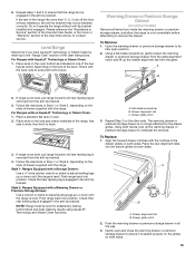
... a wrench or pliers to remove the drawer. Drawer alignment tab C. Repeat Step 2 on the size of drawer supplied with the range. Place the rear alignment tabs into position. Drawer glide notch 2. Gently open position. 2. Repeat steps 1 and 2 to ensure it is level. Level...then front to contact service. Follow the directions in one of the two figures below depending on the other side. Push range back into position. NOTE: Range must be installed correctly. Flat-blade screwdriver B. The warming drawer or premium storage drawer is no longer attached to complete the...
... a wrench or pliers to remove the drawer. Drawer alignment tab C. Repeat Step 2 on the size of drawer supplied with the range. Place the rear alignment tabs into position. Drawer glide notch 2. Gently open position. 2. Repeat steps 1 and 2 to ensure it is level. Level...then front to contact service. Follow the directions in one of the two figures below depending on the other side. Push range back into position. NOTE: Range must be installed correctly. Flat-blade screwdriver B. The warming drawer or premium storage drawer is no longer attached to complete the...
Installation Instructions
Page 14
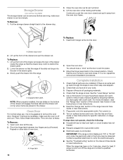
... will shut. 4. Then, follow these instructions. If it will not tip when items are now installed. Check that the edge of oven door. If range does not operate, check the following: ■ Household fuse is heavy. Storage Drawer (on some models) The storage drawer can be miswired. To Remove...Instructions. If there is cold, turn off and cool. Dispose of the Use and Care Guide or User Instructions or User Instructions. 6. If range is an extra part, go back through the steps to the drawer stop. 3. Pull the storage drawer straight back to see which step was...
... will shut. 4. Then, follow these instructions. If it will not tip when items are now installed. Check that the edge of oven door. If range does not operate, check the following: ■ Household fuse is heavy. Storage Drawer (on some models) The storage drawer can be miswired. To Remove...Instructions. If there is cold, turn off and cool. Dispose of the Use and Care Guide or User Instructions or User Instructions. 6. If range is an extra part, go back through the steps to the drawer stop. 3. Pull the storage drawer straight back to see which step was...
Installation Instructions
Page 15
...and engaged. Failure to follow these instructions can result in death or serious burns to avoid damaging the floor covering. If removing the range is engaged in the slot of the anti-tip bracket. See the "Verify Anti-Tip Bracket Is Installed and Engaged" section. 6.... Replace all parts and panels before servicing. Slide range back so rear range foot is necessary for cleaning or maintenance: For power supply cord-connected ranges: 1. Do not operate range without anti-tip bracket installed and engaged. Unplug the power supply cord. 3. Electrical ...
...and engaged. Failure to follow these instructions can result in death or serious burns to avoid damaging the floor covering. If removing the range is engaged in the slot of the anti-tip bracket. See the "Verify Anti-Tip Bracket Is Installed and Engaged" section. 6.... Replace all parts and panels before servicing. Slide range back so rear range foot is necessary for cleaning or maintenance: For power supply cord-connected ranges: 1. Do not operate range without anti-tip bracket installed and engaged. Unplug the power supply cord. 3. Electrical ...

Owners Manual
Page 1
... some models 16 Storage Drawer (on some models 17 Oven Door 17 Complete Installation 18 Moving the Range 18 IMPORTANT: Save for local electrical inspector's use. FREESTANDING ELECTRIC RANGE OWNER'S MANUAL Table of Contents RANGE SAFETY 2 Range Safety 2 RANGE MAINTENANCE AND CARE 4 Self-Cleaning Cycle (on some models 4 General Cleaning 4 INSTALLATION INSTRUCTIONS 6 REQUIREMENTS 6 Tools and...
... some models 16 Storage Drawer (on some models 17 Oven Door 17 Complete Installation 18 Moving the Range 18 IMPORTANT: Save for local electrical inspector's use. FREESTANDING ELECTRIC RANGE OWNER'S MANUAL Table of Contents RANGE SAFETY 2 Range Safety 2 RANGE MAINTENANCE AND CARE 4 Self-Cleaning Cycle (on some models 4 General Cleaning 4 INSTALLATION INSTRUCTIONS 6 REQUIREMENTS 6 Tools and...
Owners Manual
Page 2
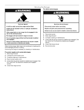
... or "WARNING." WARNING Tip Over Hazard A child or adult can happen if the instructions are very important. Re-engage anti-tip bracket if range is under the anti-tip bracket. • See Installation Instructions for details. To verify the anti-tip bracket is properly installed and engaged:... • Slide range forward. • Look for Warming or Heating the Room. The appliance, when installed, must be electrically grounded in the slot of the ...
... or "WARNING." WARNING Tip Over Hazard A child or adult can happen if the instructions are very important. Re-engage anti-tip bracket if range is under the anti-tip bracket. • See Installation Instructions for details. To verify the anti-tip bracket is properly installed and engaged:... • Slide range forward. • Look for Warming or Heating the Room. The appliance, when installed, must be electrically grounded in the slot of the ...
Owners Manual
Page 3
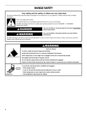
...seal. Let hot air or steam escape before removing or replacing food. � Do Not Heat Unopened Food Containers - For smart enabled ranges and ovens � Remote operation - IMPORTANT SAFETY INSTRUCTIONS � Do Not Leave Children Alone - All other flammable materials contact heating elements... foil and meat probes from steam. Children should be left alone or unattended in burns from contacting heating elements. For self-cleaning ranges - � Do Not Clean Door Gasket - For units with the utensil, the handle of a utensil should not be positioned...
...seal. Let hot air or steam escape before removing or replacing food. � Do Not Heat Unopened Food Containers - For smart enabled ranges and ovens � Remote operation - IMPORTANT SAFETY INSTRUCTIONS � Do Not Leave Children Alone - All other flammable materials contact heating elements... foil and meat probes from steam. Children should be left alone or unattended in burns from contacting heating elements. For self-cleaning ranges - � Do Not Clean Door Gasket - For units with the utensil, the handle of a utensil should not be positioned...
