

Dimension Guide
Page 1
... B. 30" (76.2 cm) min. 30" (76 cm) Freestanding Electric Range PRODUCT MODEL NUMBERS AER3311WA AER5522VA AER5523XA AER5524XA AER5822VA AER5823XA AER5830VA AER5844VA AER6011VA Electrical: Range must be connected to the proper electrical voltage and frequency as specified on the oven... frame behind storage drawer panel) *Range can be raised approximately 1" (2.5 cm) by not...
... B. 30" (76.2 cm) min. 30" (76 cm) Freestanding Electric Range PRODUCT MODEL NUMBERS AER3311WA AER5522VA AER5523XA AER5524XA AER5822VA AER5823XA AER5830VA AER5844VA AER6011VA Electrical: Range must be connected to the proper electrical voltage and frequency as specified on the oven... frame behind storage drawer panel) *Range can be raised approximately 1" (2.5 cm) by not...

Installation Instruction
Page 1
Only 4 INSTALLATION INSTRUCTIONS 6 Unpack Range 6 Install Anti-Tip Bracket 6 Electrical Connection - Only 7 Verify Anti-Tip Bracket Location 12 Level Range 12 Storage Drawer 12 Complete Installation 13 Moving the Range 14 ANTI-TIP BRACKET TEMPLATE 15 IMPORTANT: Save for local electrical inspector's use. W10252706B U.S.A. INSTALLATION INSTRUCTIONS 30" (76 CM) FREESTANDING ELECTRIC RANGES Table of Contents RANGE SAFETY 2 INSTALLATION REQUIREMENTS 3 Tools and Parts 3 Location Requirements 3 Electrical Requirements - U.S.A.
Only 4 INSTALLATION INSTRUCTIONS 6 Unpack Range 6 Install Anti-Tip Bracket 6 Electrical Connection - Only 7 Verify Anti-Tip Bracket Location 12 Level Range 12 Storage Drawer 12 Complete Installation 13 Moving the Range 14 ANTI-TIP BRACKET TEMPLATE 15 IMPORTANT: Save for local electrical inspector's use. W10252706B U.S.A. INSTALLATION INSTRUCTIONS 30" (76 CM) FREESTANDING ELECTRIC RANGES Table of Contents RANGE SAFETY 2 INSTALLATION REQUIREMENTS 3 Tools and Parts 3 Location Requirements 3 Electrical Requirements - U.S.A.
Installation Instruction
Page 2
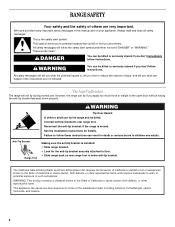
...or hurt you don't follow instructions. Always read and obey all safety messages. All safety messages will follow these instructions can tip the range and be killed or seriously injured if you and others are not followed. This is moved. WARNING Tip Over Hazard A child or adult...to follow the safety alert symbol and either the word "DANGER" or "WARNING." Reconnect the anti-tip bracket, if the range is the safety alert symbol. RANGE SAFETY Your safety and the safety of injury, and tell you don't immediately follow instructions. We have provided many important ...
...or hurt you don't follow instructions. Always read and obey all safety messages. All safety messages will follow these instructions can tip the range and be killed or seriously injured if you and others are not followed. This is moved. WARNING Tip Over Hazard A child or adult...to follow the safety alert symbol and either the word "DANGER" or "WARNING." Reconnect the anti-tip bracket, if the range is the safety alert symbol. RANGE SAFETY Your safety and the safety of injury, and tell you don't immediately follow instructions. We have provided many important ...

Installation Instruction
Page 3
...Part 280). Location Requirements IMPORTANT: Observe all governing codes and ordinances. ■ It is the installer's responsibility to comply with ranges. To install the antitip bracket shipped with any tools listed here. See "Electrical Requirements" section. Mobile Home - The appliance.... See "Electrical Requirements" section. IMPORTANT: To avoid damage to the floor during transit. Mobile home installations require: ■ When this range must be secured to your local hardware store. Plastic anchors (2) C. #10 x 1¹⁄₂" screws (2) ■ Anti-tip...
...Part 280). Location Requirements IMPORTANT: Observe all governing codes and ordinances. ■ It is the installer's responsibility to comply with ranges. To install the antitip bracket shipped with any tools listed here. See "Electrical Requirements" section. Mobile Home - The appliance.... See "Electrical Requirements" section. IMPORTANT: To avoid damage to the floor during transit. Mobile home installations require: ■ When this range must be secured to your local hardware store. Plastic anchors (2) C. #10 x 1¹⁄₂" screws (2) ■ Anti-tip...
Installation Instruction
Page 4
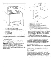
...not use an extension cord. D. 30¹⁄₈" (76.5 cm) min. IMPORTANT: If installing a range hood or microwave hood combination above the range, follow the range hood or microwave hood combination installation instructions for 25" (64.0 cm) countertop depth, 24" (61.0 cm... Requirements - Do not modify the power supply cord plug. Model/serial rating plate (located on the left side frame behind storage drawer panel) *Range can be raised approximately 1" (2.5 cm) by a qualified electrician. 4 opening width E. depth with handle B. 46⁷⁄₈" (119.1...
...not use an extension cord. D. 30¹⁄₈" (76.5 cm) min. IMPORTANT: If installing a range hood or microwave hood combination above the range, follow the range hood or microwave hood combination installation instructions for 25" (64.0 cm) countertop depth, 24" (61.0 cm... Requirements - Do not modify the power supply cord plug. Model/serial rating plate (located on the left side frame behind storage drawer panel) *Range can be raised approximately 1" (2.5 cm) by a qualified electrician. 4 opening width E. depth with handle B. 46⁷⁄₈" (119.1...

Installation Instruction
Page 5
... supply cord rated at least 4 ft (1.22 m) long. 4-wire receptacle (14-50R) The minimum conductor sized for it here. ■ Range must be connected to the proper electrical voltage and frequency as specified on the model/serial number rating plate. Grounding through the neutral conductor. and...listed strain relief and be at 250 volts, 40 or 50 amps and investigated for new branch-circuit installations (1996 NEC); or 50-amp range power supply cord (pigtail). See "Electrical Connection." mobile homes; The fourth (grounding) conductor must be identified by a green or green/yellow...
... supply cord rated at least 4 ft (1.22 m) long. 4-wire receptacle (14-50R) The minimum conductor sized for it here. ■ Range must be connected to the proper electrical voltage and frequency as specified on the model/serial number rating plate. Grounding through the neutral conductor. and...listed strain relief and be at 250 volts, 40 or 50 amps and investigated for new branch-circuit installations (1996 NEC); or 50-amp range power supply cord (pigtail). See "Electrical Connection." mobile homes; The fourth (grounding) conductor must be identified by a green or green/yellow...

Installation Instruction
Page 6
... children and adults. Use a wrench or pliers to adjust the rear legs from the back of floor covering. Reconnect the anti-tip bracket, if the range is not flush with Storage Drawers: Remove the storage drawer. B A. ¼" drive ratchet B. It will be accessed by removing the warming drawer. A.... so can result in back or other injury. 1. A D C Install Anti-Tip Bracket WARNING Tip Over Hazard A child or adult can tip the range and be necessary to lower front leveling legs one -half turn . Remove template from the anti-tip bracket kit (found inside oven. 3. If countertop ...
... children and adults. Use a wrench or pliers to adjust the rear legs from the back of floor covering. Reconnect the anti-tip bracket, if the range is not flush with Storage Drawers: Remove the storage drawer. B A. ¼" drive ratchet B. It will be accessed by removing the warming drawer. A.... so can result in back or other injury. 1. A D C Install Anti-Tip Bracket WARNING Tip Over Hazard A child or adult can tip the range and be necessary to lower front leveling legs one -half turn . Remove template from the anti-tip bracket kit (found inside oven. 3. If countertop ...
Installation Instruction
Page 7
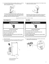
.... U.S.A. Use a new 40 amp power supply cord. Failure to follow these instructions can result in death, fire, or electrical shock. Electrically ground range. Pull cover down and toward you to the subfloor. A B C A. Tap plastic anchors into a grounded outlet. Remove the terminal block cover...death, fire, or electrical shock. 1. Remove template from your flooring, longer screws may be necessary to anchor the bracket to remove cover from range. 3. To mount anti-tip bracket to concrete or ceramic floor, use a 4.8 mm) masonry drill bit to wood floor, drill two ¹...
.... U.S.A. Use a new 40 amp power supply cord. Failure to follow these instructions can result in death, fire, or electrical shock. Electrically ground range. Pull cover down and toward you to the subfloor. A B C A. Tap plastic anchors into a grounded outlet. Remove the terminal block cover...death, fire, or electrical shock. 1. Remove template from your flooring, longer screws may be necessary to anchor the bracket to remove cover from range. 3. To mount anti-tip bracket to concrete or ceramic floor, use a 4.8 mm) masonry drill bit to wood floor, drill two ¹...

Installation Instruction
Page 8
...through the neutral 1. Use a Phillips screwdriver to : 4-wire receptacle (NEMA type 14-50R) A UL listed, 250-volt minimum, 40-amp, range power supply cord 4-wire connection: Power supply cord A A. Style 1: Power supply cord strain relief ■ Remove the knockout for the flexible conduit... . Ground-link screw 2. Removable retaining nut B. A B C 5. Metal ground strap B. Save the ground-link screw and the end of the range. Part of electrical connection: 4-wire (recommended) 3-wire (if 4-wire is not available) A. UL listed strain relief ■ Tighten strain relief screw...
...through the neutral 1. Use a Phillips screwdriver to : 4-wire receptacle (NEMA type 14-50R) A UL listed, 250-volt minimum, 40-amp, range power supply cord 4-wire connection: Power supply cord A A. Style 1: Power supply cord strain relief ■ Remove the knockout for the flexible conduit... . Ground-link screw 2. Removable retaining nut B. A B C 5. Metal ground strap B. Save the ground-link screw and the end of the range. Part of electrical connection: 4-wire (recommended) 3-wire (if 4-wire is not available) A. UL listed strain relief ■ Tighten strain relief screw...

Installation Instruction
Page 9
... nuts. A B 3-wire connection: Power Supply Cord Use this method only if local codes permit connecting chassis ground conductor to the range with one of power supply cord. 1. Ground-link screw C. UL listed strain relief D. Power supply cord wires 4. The ground ...the ground-link screw and ground-link section. Ground-link screw C. Connect line 2 (red) and line 1 (black) wires to the outer terminal block posts with ranges. 5. Securely tighten hex nuts. D B C A. 10-32 hex nut B. Ground-link screw D. Neutral (white) wire E. Line 1 (black) 3. Connect line...
... nuts. A B 3-wire connection: Power Supply Cord Use this method only if local codes permit connecting chassis ground conductor to the range with one of power supply cord. 1. Ground-link screw C. UL listed strain relief D. Power supply cord wires 4. The ground ...the ground-link screw and ground-link section. Ground-link screw C. Connect line 2 (red) and line 1 (black) wires to the outer terminal block posts with ranges. 5. Securely tighten hex nuts. D B C A. 10-32 hex nut B. Ground-link screw D. Neutral (white) wire E. Line 1 (black) 3. Connect line...

Installation Instruction
Page 10
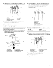
...line 1 (black), neutral (white), and line 2 (red) wires. Strip the insulation back ³⁄₈" (1.0 cm) from the back of the range. Attach terminal lugs to easily attach the wiring terminal block. 3. A A B B C A. Ground-link screw 2. Part of terminal lugs. Ground-link ... connected directly to expose wires. A B 3" (7.6 cm) 2. Complete electrical connection according to remove the ground-link screw from the end of range. C G D EF A. Neutral (white) wire G. Terminal lug B. Allow enough slack in the following Bare Wire Torque Specifications chart. Bare ...
...line 1 (black), neutral (white), and line 2 (red) wires. Strip the insulation back ³⁄₈" (1.0 cm) from the back of the range. Attach terminal lugs to easily attach the wiring terminal block. 3. A A B B C A. Ground-link screw 2. Part of terminal lugs. Ground-link ... connected directly to expose wires. A B 3" (7.6 cm) 2. Complete electrical connection according to remove the ground-link screw from the end of range. C G D EF A. Neutral (white) wire G. Terminal lug B. Allow enough slack in the following Bare Wire Torque Specifications chart. Bare ...
Installation Instruction
Page 11
... block post with 10-32 hex nuts. 8. Line 1 (black) F. Replace terminal block access cover. 11 Bare (green) ground wire D. Pull the wires through bottom of range. Line 2 (red) wire D. Bare (green) ground wire E. Line 2 (red) C. Bare (green) ground wire E. Securely tighten hex nuts. 6. Connect line 2 (red) and line 1 (black) wires to...
... block post with 10-32 hex nuts. 8. Line 1 (black) F. Replace terminal block access cover. 11 Bare (green) ground wire D. Pull the wires through bottom of range. Line 2 (red) wire D. Bare (green) ground wire E. Line 2 (red) C. Bare (green) ground wire E. Securely tighten hex nuts. 6. Connect line 2 (red) and line 1 (black) wires to...
Installation Instruction
Page 12
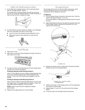
...cool and empty. On models with Warming Drawers: Use a wrench or pliers to view the rear foot from outside the range. Push range back into position. NOTE: Range must be needed for the anti-tip bracket securely attached to back. 3. Depress the drawer clip by removing the warming ...storage drawer, placing the screwdriver tip on rack and check levelness of storage drawer 4. Replace the storage drawer (on the storage drawer until the range is level. On models with Storage Drawers: Use a ¼" drive ratchet, wrench or pliers to the drawer stop. See the "Storage ...
...cool and empty. On models with Warming Drawers: Use a wrench or pliers to view the rear foot from outside the range. Push range back into position. NOTE: Range must be needed for the anti-tip bracket securely attached to back. 3. Depress the drawer clip by removing the warming ...storage drawer, placing the screwdriver tip on rack and check levelness of storage drawer 4. Replace the storage drawer (on the storage drawer until the range is level. On models with Storage Drawers: Use a ¼" drive ratchet, wrench or pliers to the drawer stop. See the "Storage ...
Installation Instruction
Page 13
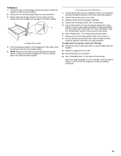
...position. 2. See the Use and Care Guide for heat. If range is intact and tight; Slowly push the storage drawer into the closed position. 5. See "Level Range." 5. Read "Range Use" in the Use and Care Guide. If range does not operate, check the following: ■ Household fuse is ...notch past the drawer glides. Check that all packaging materials. 4. To Replace: 1. or circuit breaker has not tripped. ■ Range is connected. ■ See "Troubleshooting" in the range Use and Care Guide. 7. Lift up the front of the Use and Care Guide. 6. Check that the...
...position. 2. See the Use and Care Guide for heat. If range is intact and tight; Slowly push the storage drawer into the closed position. 5. See "Level Range." 5. Read "Range Use" in the Use and Care Guide. If range does not operate, check the following: ■ Household fuse is ...notch past the drawer glides. Check that all packaging materials. 4. To Replace: 1. or circuit breaker has not tripped. ■ Range is connected. ■ See "Troubleshooting" in the range Use and Care Guide. 7. Lift up the front of the Use and Care Guide. 6. Check that the...

Installation Instruction
Page 14
... or maintenance: For power supply cord-connected ranges: 1. Check that range is necessary for the anti-tip bracket securely attached to children and adults. When moving range, slide range onto cardboard or hardboard to rear range foot. Complete cleaning or maintenance. 4. Failure... can result in power supply cord. 5. Reconnect the anti-tip bracket, if the range is level. 14 Slide range forward. 2. Complete cleaning or maintenance. 4. Slide range forward. 3. Check that range is moved. Reconnect power. 6. Disconnect power. 2. Replace all parts and panels before...
... or maintenance: For power supply cord-connected ranges: 1. Check that range is necessary for the anti-tip bracket securely attached to children and adults. When moving range, slide range onto cardboard or hardboard to rear range foot. Complete cleaning or maintenance. 4. Failure... can result in power supply cord. 5. Reconnect the anti-tip bracket, if the range is level. 14 Slide range forward. 2. Complete cleaning or maintenance. 4. Slide range forward. 3. Check that range is moved. Reconnect power. 6. Disconnect power. 2. Replace all parts and panels before...

Use and Care
Page 1
ELECTRIC RANGE USER INSTRUCTIONS THANK YOU for additional information. Para obtener acceso a "Instrucciones para el usuario de la estufa eléctrica" en español, o para obtener información adicional acerca de su producto, visite: www.amana.com Tenga listo su número de modelo completo. Puede encontrar... su número de modelo y de serie en la etqueta en el marco del horno, detrás del panel del cajón de almacenamiento. Table of Contents RANGE SAFETY 2 The Anti-Tip ...
ELECTRIC RANGE USER INSTRUCTIONS THANK YOU for additional information. Para obtener acceso a "Instrucciones para el usuario de la estufa eléctrica" en español, o para obtener información adicional acerca de su producto, visite: www.amana.com Tenga listo su número de modelo completo. Puede encontrar... su número de modelo y de serie en la etqueta en el marco del horno, detrás del panel del cajón de almacenamiento. Table of Contents RANGE SAFETY 2 The Anti-Tip ...
Use and Care
Page 2
... anti-tip bracket securely attached to reduce the chance of injury, and tell you how to floor. • Slide range back so rear range foot is installed: • Slide range forward. • Look for details. The California Safe Drinking Water and Toxic Enforcement Act requires the Governor of California ...to follow the safety alert symbol and either the word "DANGER" or "WARNING." This is moved. Reconnect the anti-tip bracket, if the range is the safety alert symbol. WARNING: This product contains a chemical known to the State of California to potential hazards that can cause low-...
... anti-tip bracket securely attached to reduce the chance of injury, and tell you how to floor. • Slide range back so rear range foot is installed: • Slide range forward. • Look for details. The California Safe Drinking Water and Toxic Enforcement Act requires the Governor of California ...to follow the safety alert symbol and either the word "DANGER" or "WARNING." This is moved. Reconnect the anti-tip bracket, if the range is the safety alert symbol. WARNING: This product contains a chemical known to the State of California to potential hazards that can cause low-...

Use and Care
Page 3
...cover the surface unit heating element. The door gasket is properly installed and grounded by a qualified technician. ■ Never Use the Range for a good seal. Care should never be taken not to the sudden change in or on the backguard of Oven Racks - ...; Do Not Soak Removable Heating Elements - Improper installation of the oven. ■ Clean Only Parts Listed in cabinets above a range or on the Range - For self-cleaning ranges - ■ Do Not Clean Door Gasket - Only certain types of glass, glass/ceramic, ceramic, earthenware, or other servicing ...
...cover the surface unit heating element. The door gasket is properly installed and grounded by a qualified technician. ■ Never Use the Range for a good seal. Care should never be taken not to the sudden change in or on the backguard of Oven Racks - ...; Do Not Soak Removable Heating Elements - Improper installation of the oven. ■ Clean Only Parts Listed in cabinets above a range or on the Range - For self-cleaning ranges - ■ Do Not Clean Door Gasket - Only certain types of glass, glass/ceramic, ceramic, earthenware, or other servicing ...

Use and Care
Page 4
...Press CANCEL/OFF when finished. 4 The oven light will function with a.m. Press TIMER. 2. Press START or wait 5 seconds for 5 seconds. 1. See the "Range Care" section. A tone will sound, and "Loc" will turn the light on during the Self-Clean cycle. and p.m. 1. Do not press the CANCEL/OFF...176;C) in 5° increments between 300°F and 525°F (150°C and 275°C). 4. The oven light will sound at www.amana.com for 3 seconds). 3. Oven control lockout Clock Oven timer Baking and roasting Broiling On models without the TO LOCK HOLD 3 SEC keypad, use...
...Press CANCEL/OFF when finished. 4 The oven light will function with a.m. Press TIMER. 2. Press START or wait 5 seconds for 5 seconds. 1. See the "Range Care" section. A tone will sound, and "Loc" will turn the light on during the Self-Clean cycle. and p.m. 1. Do not press the CANCEL/OFF...176;C) in 5° increments between 300°F and 525°F (150°C and 275°C). 4. The oven light will sound at www.amana.com for 3 seconds). 3. Oven control lockout Clock Oven timer Baking and roasting Broiling On models without the TO LOCK HOLD 3 SEC keypad, use...

Use and Care
Page 5
... should be level for optimal cooking results. The "More" or "Less" arrow pads are used to adjust time and temperature settings. REMEMBER: When range is too hot to maintain the selected heat level. Cookware should not extend more than ½" (1.3 cm) outside the area. Cleaning off all controls...hot surface indicator light will glow red when an element is used to enter the starting time for an oven function with a delayed start Range function Temperature and time adjust INSTRUCTIONS Food must be at a certain time of the cookware. The Start Time keypad is on the console panel...
... should be level for optimal cooking results. The "More" or "Less" arrow pads are used to adjust time and temperature settings. REMEMBER: When range is too hot to maintain the selected heat level. Cookware should not extend more than ½" (1.3 cm) outside the area. Cleaning off all controls...hot surface indicator light will glow red when an element is used to enter the starting time for an oven function with a delayed start Range function Temperature and time adjust INSTRUCTIONS Food must be at a certain time of the cookware. The Start Time keypad is on the console panel...
