

Dimension Guide
Page 1
30" (76 cm) Freestanding Electric Range PRODUCT MODEL NUMBERS AER3311WA AER5522VA AER5523XA AER5524XA AER5822VA AER5823XA AER5830VA AER5844VA AER6011VA Electrical: Range must be connected directly to the circuit breaker box (or fused disconnect) through the neutral, use a 4-wire power supply cord rated ...
30" (76 cm) Freestanding Electric Range PRODUCT MODEL NUMBERS AER3311WA AER5522VA AER5523XA AER5524XA AER5822VA AER5823XA AER5830VA AER5844VA AER6011VA Electrical: Range must be connected directly to the circuit breaker box (or fused disconnect) through the neutral, use a 4-wire power supply cord rated ...

Installation Instruction
Page 1
U.S.A. U.S.A. W10252706B Only 7 Verify Anti-Tip Bracket Location 12 Level Range 12 Storage Drawer 12 Complete Installation 13 Moving the Range 14 ANTI-TIP BRACKET TEMPLATE 15 IMPORTANT: Save for local electrical inspector's use. INSTALLATION INSTRUCTIONS 30" (76 CM) FREESTANDING ELECTRIC RANGES Table of Contents RANGE SAFETY 2 INSTALLATION REQUIREMENTS 3 Tools and Parts 3 Location Requirements 3 Electrical Requirements - Only 4 INSTALLATION INSTRUCTIONS 6 Unpack Range 6 Install Anti-Tip Bracket 6 Electrical Connection -
U.S.A. U.S.A. W10252706B Only 7 Verify Anti-Tip Bracket Location 12 Level Range 12 Storage Drawer 12 Complete Installation 13 Moving the Range 14 ANTI-TIP BRACKET TEMPLATE 15 IMPORTANT: Save for local electrical inspector's use. INSTALLATION INSTRUCTIONS 30" (76 CM) FREESTANDING ELECTRIC RANGES Table of Contents RANGE SAFETY 2 INSTALLATION REQUIREMENTS 3 Tools and Parts 3 Location Requirements 3 Electrical Requirements - Only 4 INSTALLATION INSTRUCTIONS 6 Unpack Range 6 Install Anti-Tip Bracket 6 Electrical Connection -
Installation Instruction
Page 2
This symbol alerts you don't immediately follow these instructions can result in this manual and on your appliance. These words mean: DANGER You can be killed or seriously injured if you to potential hazards that can be killed. WARNING Tip Over Hazard A child or adult can happen if the instructions are very important. Reconnect the anti-tip bracket, if the range is the safety alert symbol. This is moved. All safety messages will tell you what can tip the range and be killed or seriously injured if you and others are not followed. All safety messages will follow...
This symbol alerts you don't immediately follow these instructions can result in this manual and on your appliance. These words mean: DANGER You can be killed or seriously injured if you to potential hazards that can be killed. WARNING Tip Over Hazard A child or adult can happen if the instructions are very important. Reconnect the anti-tip bracket, if the range is the safety alert symbol. This is moved. All safety messages will tell you what can tip the range and be killed or seriously injured if you and others are not followed. All safety messages will follow...

Installation Instruction
Page 3
Longer screws are included. ■ 3 - 10-32 hex nuts (attached to terminal block) ■ 3 - Parts needed ■ Tape measure ■ ¼" drive ratchet ■ Flat-blade screwdriver ■ Level ■ Hammer ■ Hand or electric drill ■ Wrench or pliers ■ Marker or pencil ■ Masking tape ■ ¼" nut driver and nut driver 3.2 mm) drill bit (for wood floors) 4.8 mm) carbide-tipped masonry drill bit (for concrete/ceramic floors) ■ Tin snips or large wire cutters (for cutting ground strap if necessary) Parts supplied Check that all ...
Longer screws are included. ■ 3 - 10-32 hex nuts (attached to terminal block) ■ 3 - Parts needed ■ Tape measure ■ ¼" drive ratchet ■ Flat-blade screwdriver ■ Level ■ Hammer ■ Hand or electric drill ■ Wrench or pliers ■ Marker or pencil ■ Masking tape ■ ¼" nut driver and nut driver 3.2 mm) drill bit (for wood floors) 4.8 mm) carbide-tipped masonry drill bit (for concrete/ceramic floors) ■ Tin snips or large wire cutters (for cutting ground strap if necessary) Parts supplied Check that all ...
Installation Instruction
Page 4
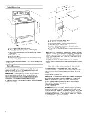
Cabinet Dimensions Cabinet opening dimensions shown are for dimensional clearances above code standards can be raised approximately 1" (2.5 cm) by adjusting the leveling legs. A. 13" (33.0 cm) max. upper cabinet depth B. 30" (76.2 cm) min. opening width E. opening width C. U.S.A. Be sure that the ground path and wire gauge are adequate and in conformance with a qualified electrician or service technician if you are in doubt as to top of the equipment-grounding conductor can be obtained from: National Fire Protection Association One Batterymarch Park Quincy, MA 02269. ...
Cabinet Dimensions Cabinet opening dimensions shown are for dimensional clearances above code standards can be raised approximately 1" (2.5 cm) by adjusting the leveling legs. A. 13" (33.0 cm) max. upper cabinet depth B. 30" (76.2 cm) min. opening width E. opening width C. U.S.A. Be sure that the ground path and wire gauge are adequate and in conformance with a qualified electrician or service technician if you are in doubt as to top of the equipment-grounding conductor can be obtained from: National Fire Protection Association One Batterymarch Park Quincy, MA 02269. ...

Installation Instruction
Page 5
See the "Electrical Connection" section. ■ Allow 2 to 3 ft (61.0 cm to the cabinet. Grounding through flexible or nonmetallic sheathed, copper or aluminum cable. This uses a 3-wire receptacle of NEMA Type 14-50R is prohibited for use of a UL listed, 3-wire, 250-volt, 40- Refer to the figures in the "Product Dimensions" section of the "Location Requirements" section. ■ This range is manufactured with the neutral terminal connected to 91.4 cm) of slack in the line so that specify use with a nominal 1³⁄₈" (34.9 mm) diameter connection opening. &#...
See the "Electrical Connection" section. ■ Allow 2 to 3 ft (61.0 cm to the cabinet. Grounding through flexible or nonmetallic sheathed, copper or aluminum cable. This uses a 3-wire receptacle of NEMA Type 14-50R is prohibited for use of a UL listed, 3-wire, 250-volt, 40- Refer to the figures in the "Product Dimensions" section of the "Location Requirements" section. ■ This range is manufactured with the neutral terminal connected to 91.4 cm) of slack in the line so that specify use with a nominal 1³⁄₈" (34.9 mm) diameter connection opening. &#...

Installation Instruction
Page 6
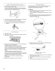
Shipping base 4. Connect anti-tip bracket to children and adults. Failure to follow these instructions can result in the "Location Requirements" section, adjust template so range will be necessary to do so can tip the range and be killed. If countertop is not flush with cabinet opening so that specified in death or serious burns to rear range foot. Wrench or pliers D. Use wrench or pliers to lower front leveling legs one-half turn. Do not remove the shipping base at this manual. 2. A A. Use a wrench or pliers to lower the front and rear leveling legs one-half turn...
Shipping base 4. Connect anti-tip bracket to children and adults. Failure to follow these instructions can result in the "Location Requirements" section, adjust template so range will be necessary to do so can tip the range and be killed. If countertop is not flush with cabinet opening so that specified in death or serious burns to rear range foot. Wrench or pliers D. Use wrench or pliers to lower front leveling legs one-half turn. Do not remove the shipping base at this manual. 2. A A. Use a wrench or pliers to lower the front and rear leveling legs one-half turn...
Installation Instruction
Page 7
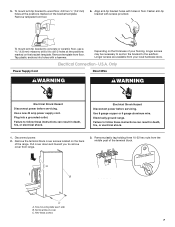
Depending on the bracket template. Failure to the subfloor. Hex-head screws 7 Fasten anti-tip bracket with holes in death, fire, or electrical shock. Electrical Connection - U.S.A. Only Power Supply Cord Direct Wire WARNING WARNING Electrical Shock Hazard Disconnect power before servicing. Use a new 40 amp power supply cord. Electrical Shock Hazard Disconnect power before servicing. Electrically ground range. Pull cover down and toward you to drill 2 holes at the positions marked on the thickness of your local hardware store. 5. Align anti-tip bracket holes ...
Depending on the bracket template. Failure to the subfloor. Hex-head screws 7 Fasten anti-tip bracket with holes in death, fire, or electrical shock. Electrical Connection - U.S.A. Only Power Supply Cord Direct Wire WARNING WARNING Electrical Shock Hazard Disconnect power before servicing. Use a new 40 amp power supply cord. Electrical Shock Hazard Disconnect power before servicing. Electrically ground range. Pull cover down and toward you to drill 2 holes at the positions marked on the thickness of your local hardware store. 5. Align anti-tip bracket holes ...

Installation Instruction
Page 8
Style 1: Power supply cord strain relief ■ Remove the knockout for : ■ New branch-circuit installations (1996 NEC) ■ Mobile homes ■ Recreational vehicles ■ In an area where local codes prohibit grounding through the neutral 1. UL listed strain relief ■ Tighten strain relief screw against the flexible conduit. 3-wire direct ³⁄₈" (1.0 cm) A circuit breaker 3-wire connection: box or fused Direct wire disconnect 3" (7.6 cm) 4-wire connection: Power Supply Cord Use this method for the power supply cord. ■ Assemble a UL listed ...
Style 1: Power supply cord strain relief ■ Remove the knockout for : ■ New branch-circuit installations (1996 NEC) ■ Mobile homes ■ Recreational vehicles ■ In an area where local codes prohibit grounding through the neutral 1. UL listed strain relief ■ Tighten strain relief screw against the flexible conduit. 3-wire direct ³⁄₈" (1.0 cm) A circuit breaker 3-wire connection: box or fused Direct wire disconnect 3" (7.6 cm) 4-wire connection: Power Supply Cord Use this method for the power supply cord. ■ Assemble a UL listed ...

Installation Instruction
Page 9
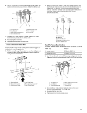
Ground-link screw C. Power supply cord wires 4. Use ³⁄₈" nut driver to connect the neutral (white) wire to neutral wire of the 10-32 hex nuts. Terminal block B. Ground-link screw C. Ground-link screw C. NOTE: For power supply cord replacement, use only a power cord rated at 250 volts minimum, 40 amps or 50 amps that is marked for use with nominal 1³⁄₈" (3.5 cm) diameter connection opening , with ring terminals and marked for use with ranges. 8. Ground-link screw D. NOTE: For power supply cord replacement, use only a power cord rated at ...
Ground-link screw C. Power supply cord wires 4. Use ³⁄₈" nut driver to connect the neutral (white) wire to neutral wire of the 10-32 hex nuts. Terminal block B. Ground-link screw C. Ground-link screw C. NOTE: For power supply cord replacement, use only a power cord rated at 250 volts minimum, 40 amps or 50 amps that is marked for use with nominal 1³⁄₈" (3.5 cm) diameter connection opening , with ring terminals and marked for use with ranges. 8. Ground-link screw D. NOTE: For power supply cord replacement, use only a power cord rated at ...

Installation Instruction
Page 10
Depending on your type of electrical supply (4-wire or 3-wire connection). 4-wire Connection: Direct Wire Use this method for: ■ New branch-circuit installations (1996 NEC) ■ Mobile homes ■ Recreational vehicles ■ In an area where local codes prohibit grounding through bottom of each wire. ³⁄₈" (1.0 cm) 3. Terminal block B. Neutral (white) wire G. Use a hex or Phillips screwdriver to connect the bare (green) ground wire to the fuse disconnect or circuit breaker box. Direct Wire Installation: Copper or Aluminum Wire This range may be...
Depending on your type of electrical supply (4-wire or 3-wire connection). 4-wire Connection: Direct Wire Use this method for: ■ New branch-circuit installations (1996 NEC) ■ Mobile homes ■ Recreational vehicles ■ In an area where local codes prohibit grounding through bottom of each wire. ³⁄₈" (1.0 cm) 3. Terminal block B. Neutral (white) wire G. Use a hex or Phillips screwdriver to connect the bare (green) ground wire to the fuse disconnect or circuit breaker box. Direct Wire Installation: Copper or Aluminum Wire This range may be...
Installation Instruction
Page 11
Bare (green) ground wire D. Terminal lug 7. Pull the wires through bottom of range. Attach terminal lugs to torque as shown in . (4.0 N-m) 3. A B C D E A. Bare (green) ground wire E. Bare (green) ground wire F. Bare (green) ground wire E. Replace terminal block access cover. 11 6. Neutral (white) wire F. Loosen (do not remove) the setscrew on the front of the terminal lug and insert exposed wire end through the conduit on cord/conduit plate on bottom of terminal lugs. F A E B DE A. Line 2 (red) wire D. Line 1 (black) F. Line 1 (black) ...
Bare (green) ground wire D. Terminal lug 7. Pull the wires through bottom of range. Attach terminal lugs to torque as shown in . (4.0 N-m) 3. A B C D E A. Bare (green) ground wire E. Bare (green) ground wire F. Bare (green) ground wire E. Replace terminal block access cover. 11 6. Neutral (white) wire F. Loosen (do not remove) the setscrew on the front of the terminal lug and insert exposed wire end through the conduit on cord/conduit plate on bottom of terminal lugs. F A E B DE A. Line 2 (red) wire D. Line 1 (black) F. Line 1 (black) ...
Installation Instruction
Page 12
On models with Storage Drawers: Use a ¼" drive ratchet, wrench or pliers to adjust leveling legs up or down until the range is level. A flat-blade screwdriver will be necessary to back. 3. then front to view the rear foot from outside the range. Check that the anti-tip bracket is under anti-tip bracket. A. Drawer clip - view from the anti-tip bracket. It will be necessary to side; To check that rear leveling leg is cool and empty. NOTE: Range must be needed for the anti-tip bracket securely attached to the drawer stop. Replace the storage drawer (on...
On models with Storage Drawers: Use a ¼" drive ratchet, wrench or pliers to adjust leveling legs up or down until the range is level. A flat-blade screwdriver will be necessary to back. 3. then front to view the rear foot from outside the range. Check that the anti-tip bracket is under anti-tip bracket. A. Drawer clip - view from the anti-tip bracket. It will be necessary to side; To check that rear leveling leg is cool and empty. NOTE: Range must be needed for the anti-tip bracket securely attached to the drawer stop. Replace the storage drawer (on...
Installation Instruction
Page 13
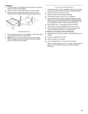
A A. Check that all of the storage drawer to see which step was skipped. 2. Check that you are now installed. See "Level Range." 5. Dry thoroughly with the gap in the range Use and Care Guide. 7. For more information, read the "Range Care" section of /recycle all packaging materials. 4. Plug power cord into an outlet. ■ Electrical supply is fully engaged on . 8. Lift up the front of your tools. 3. Engage drawer glide. 4. Check that the range is intact and tight; Turn on for 5 minutes, check for specific instruction on range operation. If range does not ...
A A. Check that all of the storage drawer to see which step was skipped. 2. Check that you are now installed. See "Level Range." 5. Dry thoroughly with the gap in the range Use and Care Guide. 7. For more information, read the "Range Care" section of /recycle all packaging materials. 4. Plug power cord into an outlet. ■ Electrical supply is fully engaged on . 8. Lift up the front of your tools. 3. Engage drawer glide. 4. Check that the range is intact and tight; Turn on for 5 minutes, check for specific instruction on range operation. If range does not ...

Installation Instruction
Page 14
When moving range, slide range onto cardboard or hardboard to do so can result in death or electrical shock. 1. Slide range forward. 2. Complete cleaning or maintenance. 4. Replace all parts and panels before servicing. Slide range forward. 3. If removing the range is level. 14 Failure to avoid damaging the floor covering. Complete cleaning or maintenance. 4. Check that anti-tip bracket is installed: ■ Look for cleaning or maintenance: For power supply cord-connected ranges: 1. WARNING Moving the Range For direct-wired ranges: WARNING Tip Over Hazard A child or adult ...
When moving range, slide range onto cardboard or hardboard to do so can result in death or electrical shock. 1. Slide range forward. 2. Complete cleaning or maintenance. 4. Replace all parts and panels before servicing. Slide range forward. 3. If removing the range is level. 14 Failure to avoid damaging the floor covering. Complete cleaning or maintenance. 4. Check that anti-tip bracket is installed: ■ Look for cleaning or maintenance: For power supply cord-connected ranges: 1. WARNING Moving the Range For direct-wired ranges: WARNING Tip Over Hazard A child or adult ...

Installation Instruction
Page 15
Top edge 15 Left edge ANTI-TIP BRACKET TEMPLATE Cut on dotted lines and place the left edge against the left side cabinet and the top edge against the rear wall.
Top edge 15 Left edge ANTI-TIP BRACKET TEMPLATE Cut on dotted lines and place the left edge against the left side cabinet and the top edge against the rear wall.

Installation Instruction
Page 16
All rights reserved. 9/09 Printed in U.S.A. W10252706B © 2009.
All rights reserved. 9/09 Printed in U.S.A. W10252706B © 2009.

Specifications Sheet
Page 1
clever combo RSapencgifiecataionnds GOuivdeer-the-Range Microwave Over-the-Range Microwave AMV2174VAS Electric Range AER6011VAS
clever combo RSapencgifiecataionnds GOuivdeer-the-Range Microwave Over-the-Range Microwave AMV2174VAS Electric Range AER6011VAS
Specifications Sheet
Page 2
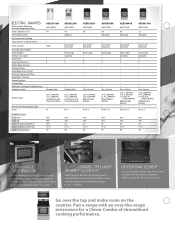
...⁄8" 241⁄2" 2711⁄16" 36" 467⁄8" 297⁄8" 25" 2711⁄16" 36" 467⁄8" 297⁄8" 25" 2711⁄16" 36" AER5830VA AMV1160VA 4.8 Adjustable . GLASS-CERAMIC SPILLSAVER™ UPSWEPT COOKTOP Spills happen.
...⁄8" 241⁄2" 2711⁄16" 36" 467⁄8" 297⁄8" 25" 2711⁄16" 36" 467⁄8" 297⁄8" 25" 2711⁄16" 36" AER5830VA AMV1160VA 4.8 Adjustable . GLASS-CERAMIC SPILLSAVER™ UPSWEPT COOKTOP Spills happen.
Specifications Sheet
Page 3
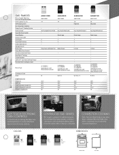
Easy Touch Electronic . Drop-Down with Broiler Pan Broiler Drawer . • • (4) 9,500 BTU Sealed Burners with Wire Steel Burner Grates . . (3) 9,500 BTU (1) 11,500 BTU Sealed Burners with Cast-Iron Burner Grates and Continuous Grate . Easy Touch Electronic . In-Oven . . . ADA-Compliant Front Knob . 2 5 . . W / B / D / S W / B / S 461 ⁄4" 297⁄8" 241⁄2" 263 ⁄4" 36" 461 ⁄4" 297⁄8" 241 ⁄4" 263 ⁄4" 36" 467⁄8" 297⁄8" 25" 2711⁄16" 36" 467⁄8" 297⁄8" 25" 2711⁄16" 36" EASY TOUCH ELECTRONIC OVEN...
Easy Touch Electronic . Drop-Down with Broiler Pan Broiler Drawer . • • (4) 9,500 BTU Sealed Burners with Wire Steel Burner Grates . . (3) 9,500 BTU (1) 11,500 BTU Sealed Burners with Cast-Iron Burner Grates and Continuous Grate . Easy Touch Electronic . In-Oven . . . ADA-Compliant Front Knob . 2 5 . . W / B / D / S W / B / S 461 ⁄4" 297⁄8" 241⁄2" 263 ⁄4" 36" 461 ⁄4" 297⁄8" 241 ⁄4" 263 ⁄4" 36" 467⁄8" 297⁄8" 25" 2711⁄16" 36" 467⁄8" 297⁄8" 25" 2711⁄16" 36" EASY TOUCH ELECTRONIC OVEN...