Installation Manual
Page 1
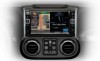
Compatibility is only expected to lead to injury or property damage. Alpine Electronics bears no responsibility for improvement. Ignoring the content marked by this indication and using the product incorrectly is not guaranteed if the manufacturer has ... Ignoring the content marked by the store that you use this product, be sure to property. Introduction ˜ Design and specifications are listed below. Jeep Wrangler X009-WRA 9" Installation Manual ˜ Model: Wrangler ˜ Model Year: 2011-UP WRANGLER Jeep Wrangler ˜ 1/13 Jeep Model...
Compatibility is only expected to lead to injury or property damage. Alpine Electronics bears no responsibility for improvement. Ignoring the content marked by this indication and using the product incorrectly is not guaranteed if the manufacturer has ... Ignoring the content marked by the store that you use this product, be sure to property. Introduction ˜ Design and specifications are listed below. Jeep Wrangler X009-WRA 9" Installation Manual ˜ Model: Wrangler ˜ Model Year: 2011-UP WRANGLER Jeep Wrangler ˜ 1/13 Jeep Model...

Installation Manual
Page 2
... not cut the insulation on a cord and take power from the negative terminal of these small objects is forbidden. interfere with the operation of Precautions WRANGLER Jeep Wrangler ˜ 2/13 Forbidden Forbidden Indicates actions that are mandatory (must not be performed) Marks content that disassembly is swallowed, consult with the specified current...
... not cut the insulation on a cord and take power from the negative terminal of these small objects is forbidden. interfere with the operation of Precautions WRANGLER Jeep Wrangler ˜ 2/13 Forbidden Forbidden Indicates actions that are mandatory (must not be performed) Marks content that disassembly is swallowed, consult with the specified current...

Installation Manual
Page 3
... steering wheel, brakes, fuel tank, or the like , could lead to fire or damage equipment. Doing so could lead to electric shock or fire. WRANGLER Jeep Wrangler ˜ 3/13 When installing and grounding the product, do not use any of the bolts or nuts of the airbag and lead to an accident...
... steering wheel, brakes, fuel tank, or the like , could lead to fire or damage equipment. Doing so could lead to electric shock or fire. WRANGLER Jeep Wrangler ˜ 3/13 When installing and grounding the product, do not use any of the bolts or nuts of the airbag and lead to an accident...

Installation Manual
Page 7
WRANGLER Jeep Wrangler ˜ 7/13 4 Remove the dash panel. 2 Remove the knee cover panel and extract 2 x 7mm screws located to the right and left sides of the steering wheel column. 3 Remove the window switch pod using a panel removing tool and extract 1 x 7mm screw. Factory Unit Disassembly Process 1 Remove the rubber cover from the top center storage area and extract 1 x 7mm screw.
WRANGLER Jeep Wrangler ˜ 7/13 4 Remove the dash panel. 2 Remove the knee cover panel and extract 2 x 7mm screws located to the right and left sides of the steering wheel column. 3 Remove the window switch pod using a panel removing tool and extract 1 x 7mm screw. Factory Unit Disassembly Process 1 Remove the rubber cover from the top center storage area and extract 1 x 7mm screw.

Installation Manual
Page 8
..., click log in. 6 Once Programing is already installed" appears. Programming the iDatalink Maestro Module 1 INSTALL THE WEBLINK PLUG-IN Go to : idatalinkmaestro.com/login. WRANGLER Jeep Wrangler ˜ 8/13 3 CONNECT YOUR MAESTRO MODULE Use the included USB cable to connect your Maestro module to your username and password, then click OK. 2 REGISTER...
..., click log in. 6 Once Programing is already installed" appears. Programming the iDatalink Maestro Module 1 INSTALL THE WEBLINK PLUG-IN Go to : idatalinkmaestro.com/login. WRANGLER Jeep Wrangler ˜ 8/13 3 CONNECT YOUR MAESTRO MODULE Use the included USB cable to connect your Maestro module to your username and password, then click OK. 2 REGISTER...

Installation Manual
Page 9
Installation Instructions 1 Attach the Maestro to the factory harness and secure it. WRANGLER Jeep Wrangler ˜ 9/13 4 Place GPS antenna next to the instrument panel as illustrated and run the cable to the radio cavity. 2 Mount the microphone as illustrated and run the cable to the radio cavity. 5 Plug the OBDII connector on to the OBDII port below the driver side dash and run the extension to the radio cavity. 3 Connect the main harness, antenna, and other adapters to the main harness.
Installation Instructions 1 Attach the Maestro to the factory harness and secure it. WRANGLER Jeep Wrangler ˜ 9/13 4 Place GPS antenna next to the instrument panel as illustrated and run the cable to the radio cavity. 2 Mount the microphone as illustrated and run the cable to the radio cavity. 5 Plug the OBDII connector on to the OBDII port below the driver side dash and run the extension to the radio cavity. 3 Connect the main harness, antenna, and other adapters to the main harness.
Installation Manual
Page 10
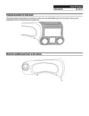
Mount the modified panel back on the vehicle. Remove the highlighted area by cutting along the dashed line. WRANGLER Jeep Wrangler ˜ 10/13 Trimming procedure for dash panel The factory dash panel needs to be trimmed to allow the new X009-WRA bezel to fit into place.
Mount the modified panel back on the vehicle. Remove the highlighted area by cutting along the dashed line. WRANGLER Jeep Wrangler ˜ 10/13 Trimming procedure for dash panel The factory dash panel needs to be trimmed to allow the new X009-WRA bezel to fit into place.

Installation Manual
Page 11
... of X009 headunit. Mount the X009 headunit using the provided screws. Mount vents on the lock tab and turning right. WRANGLER Jeep Wrangler ˜ 11/13 Installation Instructions 1 Remove the vents from the OEM radio bracket and remove it. 6 Connect the radio bezel and snap it into place. 2 A/C A/C 3 Use a cutting tool to the X009-WRA bezel...
... of X009 headunit. Mount the X009 headunit using the provided screws. Mount vents on the lock tab and turning right. WRANGLER Jeep Wrangler ˜ 11/13 Installation Instructions 1 Remove the vents from the OEM radio bracket and remove it. 6 Connect the radio bezel and snap it into place. 2 A/C A/C 3 Use a cutting tool to the X009-WRA bezel...
Installation Manual
Page 12
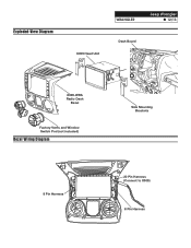
Exploded-View Diagram WRANGLER Jeep Wrangler ˜ 12/13 X009 Head Unit Dash Board X009-WRA Radio Dash Bezel Factory Vents and Window Switch Pod (not included) Bezel Wiring Diagram 8 Pin Harness A/C Side Mounting Brackets 20 Pin Harness (Connect to X009) 8 Pin Harness
Exploded-View Diagram WRANGLER Jeep Wrangler ˜ 12/13 X009 Head Unit Dash Board X009-WRA Radio Dash Bezel Factory Vents and Window Switch Pod (not included) Bezel Wiring Diagram 8 Pin Harness A/C Side Mounting Brackets 20 Pin Harness (Connect to X009) 8 Pin Harness
Installation Manual
Page 13
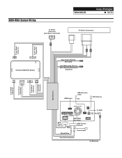
X009-WRA System Wiring To ODB II Connector (2-pin Black Connector) WRANGLER Jeep Wrangler ˜ 13/13 To Vehicle Connectors 10-pin Black Connector 18-pin Black Connector 3-pin Black Connector 10-pin Green Connector 3-pin Black Connector 4-pin ... Module Blue Power Antenna (Not used) Blue/White Amp Turn-on (Use only with aftermarket ampli ers) HDMI Input USB Extension Cable Aux GPS Antenna X009 Head Unit To SXM X009 Power Harness Green/ White Speed Pulse X009-WRA Key Panel X009 Camera Harness Camera Input 4-pin Data Connector 3.5 Mini plug
X009-WRA System Wiring To ODB II Connector (2-pin Black Connector) WRANGLER Jeep Wrangler ˜ 13/13 To Vehicle Connectors 10-pin Black Connector 18-pin Black Connector 3-pin Black Connector 10-pin Green Connector 3-pin Black Connector 4-pin ... Module Blue Power Antenna (Not used) Blue/White Amp Turn-on (Use only with aftermarket ampli ers) HDMI Input USB Extension Cable Aux GPS Antenna X009 Head Unit To SXM X009 Power Harness Green/ White Speed Pulse X009-WRA Key Panel X009 Camera Harness Camera Input 4-pin Data Connector 3.5 Mini plug
