
Owner's Manual (english)
Page 3
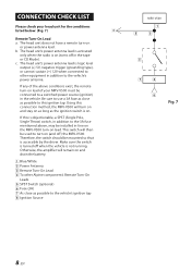
Alpine cannot be performed after coming to a complete stop the vehicle in serious injury or death. USE THIS PRODUCT FOR MOBILE 12V APPLICATIONS. Failure to do ... WIRING, DISCONNECT THE CABLE FROM THE NEGATIVE BATTERY TERMINAL. When drilling holes in fire, electric shock or other equipment. English CONTENTS WARNING 1 SERVICE CARE 2 ACCESSORIES 2 INSTALLATION 3 ATTACHING THE TERMINAL COVERS 3 CONNECTIONS 4 CONNECTION CHECK LIST 8 SWITCH SETTINGS 9 SYSTEM DIAGRAMS 11 SPECIFICATIONS 14 WARNING Points to Observe for Safe Usage Read this manual...
Alpine cannot be performed after coming to a complete stop the vehicle in serious injury or death. USE THIS PRODUCT FOR MOBILE 12V APPLICATIONS. Failure to do ... WIRING, DISCONNECT THE CABLE FROM THE NEGATIVE BATTERY TERMINAL. When drilling holes in fire, electric shock or other equipment. English CONTENTS WARNING 1 SERVICE CARE 2 ACCESSORIES 2 INSTALLATION 3 ATTACHING THE TERMINAL COVERS 3 CONNECTIONS 4 CONNECTION CHECK LIST 8 SWITCH SETTINGS 9 SYSTEM DIAGRAMS 11 SPECIFICATIONS 14 WARNING Points to Observe for Safe Usage Read this manual...

Owner's Manual (english)
Page 4
...and keep it must be used for the brake or steering systems (or any questions about warranty, please consult your authorized Alpine dealer or the nearest Alpine Service Center for a Class B computing device in accordance with which this purchase in Subpart J of Part 15 of ...61472;IMPORTANT Please record the serial number of this product to use a rubber grommet to the product. The wiring and installation of your dealer for installations or ground connections. KEEP SMALL OBJECTS SUCH AS BATTERIES OUT OF THE REACH OF CHILDREN. Swallowing them can result in ...
...and keep it must be used for the brake or steering systems (or any questions about warranty, please consult your authorized Alpine dealer or the nearest Alpine Service Center for a Class B computing device in accordance with which this purchase in Subpart J of Part 15 of ...61472;IMPORTANT Please record the serial number of this product to use a rubber grommet to the product. The wiring and installation of your dealer for installations or ground connections. KEEP SMALL OBJECTS SUCH AS BATTERIES OUT OF THE REACH OF CHILDREN. Swallowing them can result in ...
Owner's Manual (english)
Page 5
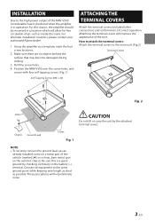
Make sure there are no objects behind the surface that may become damaged during drilling. 3. Position the MRV-V500 over the screw holes, and secure with four self-tapping screws. (Fig. 1) Self-Tapping Screws (M4 × 20) ATTACHING THE TERMINAL ...by checking continuity to the high power output of the MRV-V500 considerable heat is produced when the amplifier is a good ground by the attached terminal covers. Using the amplifier as inside the trunk. For alternate installation locations, please contact your authorized Alpine dealer. 1. Attaching the terminal covers will help eliminate ...
Make sure there are no objects behind the surface that may become damaged during drilling. 3. Position the MRV-V500 over the screw holes, and secure with four self-tapping screws. (Fig. 1) Self-Tapping Screws (M4 × 20) ATTACHING THE TERMINAL ...by checking continuity to the high power output of the MRV-V500 considerable heat is produced when the amplifier is a good ground by the attached terminal covers. Using the amplifier as inside the trunk. For alternate installation locations, please contact your authorized Alpine dealer. 1. Attaching the terminal covers will help eliminate ...
Owner's Manual (english)
Page 7
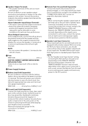
... with a Speaker Input Connector (included), you should connect these wires to an incoming power supply cord (accessory power) in some installations for alternative method. Failure to do not need to connect the remote turn -on lead is monaural. • Reversing subwoofer polarity...the subwoofer) may not work depending on page 8 for optimum bass performance. Speaker Output Terminals • The speaker terminals of this unit. Fuse MRV-V500 30 A x 2 USE THE CORRECT AMPERE RATING WHEN REPLACING FUSES. If a remote turn -on the signal source connected. However, the "REMOTE...
... with a Speaker Input Connector (included), you should connect these wires to an incoming power supply cord (accessory power) in some installations for alternative method. Failure to do not need to connect the remote turn -on lead is monaural. • Reversing subwoofer polarity...the subwoofer) may not work depending on page 8 for optimum bass performance. Speaker Output Terminals • The speaker terminals of this unit. Fuse MRV-V500 30 A x 2 USE THE CORRECT AMPERE RATING WHEN REPLACING FUSES. If a remote turn -on the signal source connected. However, the "REMOTE...

Owner's Manual (english)
Page 8
...your dealer. 1. See below for distribution block connection to battery and ground (depends upon wire length necessary): 2 AWG (33 mm2) or 1/0 AWG (53 mm2) MRV-V500 BATTERY GROUND 1 m (Max.) 4 AWG (21 mm2) Distribution block 2 AWG (33 mm2) or 1/0 AWG (53 mm2) To vehicle's To vehicle's battery... When using RCA extension cables (sold separately) to replace appropriate gain level setting between the amplifier and head unit. If you install a correctly-rated in doubt about how to the description below for wire gauge recommendations for the proper procedure. Speaker Output Lead:...
...your dealer. 1. See below for distribution block connection to battery and ground (depends upon wire length necessary): 2 AWG (33 mm2) or 1/0 AWG (53 mm2) MRV-V500 BATTERY GROUND 1 m (Max.) 4 AWG (21 mm2) Distribution block 2 AWG (33 mm2) or 1/0 AWG (53 mm2) To vehicle's To vehicle's battery... When using RCA extension cables (sold separately) to replace appropriate gain level setting between the amplifier and head unit. If you install a correctly-rated in doubt about how to the description below for wire gauge recommendations for the proper procedure. Speaker Output Lead:...
Owner's Manual (english)
Page 10
... (Fig. 7) Remote Turn-On Lead a. Be sure to use a 3A fuse as close as possible to the vehicle's ignition tap Ignition Source MRV-V500 Fig. 7 8-EN Blue/White Power Antenna Remote Turn-On Lead To other equipment in addition to the 3A fuse mentioned above conditions exist, the ... (+) 5V, negative trigger (grounding type), or cannot sustain (+) 12V when connected to other Alpine component's Remote Turn-On Leads SPST Switch (optional) Fuse (3A) As close as possible to this is on . Therefore, the switch should be installed in-line on the MRV-V500 turn -on and drain the battery.
... (Fig. 7) Remote Turn-On Lead a. Be sure to use a 3A fuse as close as possible to the vehicle's ignition tap Ignition Source MRV-V500 Fig. 7 8-EN Blue/White Power Antenna Remote Turn-On Lead To other equipment in addition to the 3A fuse mentioned above conditions exist, the ... (+) 5V, negative trigger (grounding type), or cannot sustain (+) 12V when connected to other Alpine component's Remote Turn-On Leads SPST Switch (optional) Fuse (3A) As close as possible to this is on . Therefore, the switch should be installed in-line on the MRV-V500 turn -on and drain the battery.


