
Owner's Manual (english)
Page 1
.... 19145 Gramercy Place, Torrance, California 90501, U.S.A. www.alpine.co.uk ALPINE ELECTRONICS FRANCE S.A.R.L. (RCS PONTOISE B 338 101 280) 98, Rue de la Belle Etoile, Z.I. FOR CAR USE ONLY/POUR APPLICATION AUTOMOBILE/PARA USO EN AUTOMÓVILES EN MRV-V500 FR 4 CHANNEL + MONO POWER AMPLIFIER ES • OWNER'S MANUAL Please read before using this equipment. • MODE D'EMPLOI Veuillez lire avant d'utiliser cet appareil. •...
.... 19145 Gramercy Place, Torrance, California 90501, U.S.A. www.alpine.co.uk ALPINE ELECTRONICS FRANCE S.A.R.L. (RCS PONTOISE B 338 101 280) 98, Rue de la Belle Etoile, Z.I. FOR CAR USE ONLY/POUR APPLICATION AUTOMOBILE/PARA USO EN AUTOMÓVILES EN MRV-V500 FR 4 CHANNEL + MONO POWER AMPLIFIER ES • OWNER'S MANUAL Please read before using this equipment. • MODE D'EMPLOI Veuillez lire avant d'utiliser cet appareil. •...
Owner's Manual (english)
Page 3
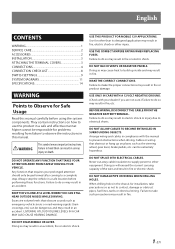
..., etc. Alpine cannot be extremely hazardous. DO NOT BLOCK VENTS OR RADIATOR PANELS. USE ONLY IN CARS WITH A 12 VOLT NEGATIVE GROUND. (Check with the manual to prevent obstructions when driving. BEFORE WIRING, DISCONNECT THE CABLE FROM THE NEGATIVE BATTERY TERMINAL. Failure to do so may result in fire or electric shock. Never cut away cable insulation to supply power to other...
..., etc. Alpine cannot be extremely hazardous. DO NOT BLOCK VENTS OR RADIATOR PANELS. USE ONLY IN CARS WITH A 12 VOLT NEGATIVE GROUND. (Check with the manual to prevent obstructions when driving. BEFORE WIRING, DISCONNECT THE CABLE FROM THE NEGATIVE BATTERY TERMINAL. Failure to do so may result in fire or electric shock. Never cut away cable insulation to supply power to other...

Owner's Manual (english)
Page 4
... 1 SET • Speaker Input Connector 1 • Hexagon Wrench (Large/Small 1 SET 2-EN CAUTION This symbol means important instructions. This will prevent crimping and damage to the product. This may result in accordance with the specifications in serious injury. DO NOT USE BOLTS OR NUTS IN THE BRAKE OR STEERING SYSTEMS TO MAKE GROUND CONNECTIONS. Bolts or nuts used properly in product failure. Using such parts...
... 1 SET • Speaker Input Connector 1 • Hexagon Wrench (Large/Small 1 SET 2-EN CAUTION This symbol means important instructions. This will prevent crimping and damage to the product. This may result in accordance with the specifications in serious injury. DO NOT USE BOLTS OR NUTS IN THE BRAKE OR STEERING SYSTEMS TO MAKE GROUND CONNECTIONS. Bolts or nuts used properly in product failure. Using such parts...
Owner's Manual (english)
Page 5
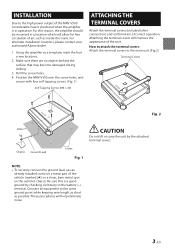
... help eliminate noise. 3-EN Using the amplifier as a template, mark the four screw locations. 2. Drill the screw holes. 4. INSTALLATION Due to the same ground point while keeping wire length as short as possible. For this is in a location which will allow for free circulation of the MRV-V500 considerable heat is produced when the amplifier is a good ground by checking continuity to the main unit...
... help eliminate noise. 3-EN Using the amplifier as a template, mark the four screw locations. 2. Drill the screw holes. 4. INSTALLATION Due to the same ground point while keeping wire length as short as possible. For this is in a location which will allow for free circulation of the MRV-V500 considerable heat is produced when the amplifier is a good ground by checking continuity to the main unit...
Owner's Manual (english)
Page 6
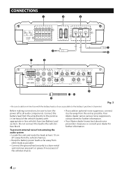
... -line vehicle's fuse (see Battery Lead section). Before making connections, be sure to turn the power off to the vehicle's fuse block. To prevent external noise from entering the audio system • Locate the unit and route the leads at least 10 cm (4") away from the vehicle's harness. • Keep the battery power leads as far away from other leads as possible. • Connect the ground...
... -line vehicle's fuse (see Battery Lead section). Before making connections, be sure to turn the power off to the vehicle's fuse block. To prevent external noise from entering the audio system • Locate the unit and route the leads at least 10 cm (4") away from the vehicle's harness. • Keep the battery power leads as far away from other leads as possible. • Connect the ground...
Owner's Manual (english)
Page 7
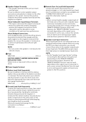
... follows: MRV-V500 4 AWG/21 mm2 Remote Turn-On Lead (Sold Separately) Connect this unit are for alternative method. See below for optimum bass performance. Ground all your audio components to the same point on the chassis to the subwoofer) may result in -line fuse with preamp outputs. NOTE: • When connecting the speaker output leads of the head unit to this unit with a Speaker Input Connector (included), you should connect these wires to...
... follows: MRV-V500 4 AWG/21 mm2 Remote Turn-On Lead (Sold Separately) Connect this unit are for alternative method. See below for optimum bass performance. Ground all your audio components to the same point on the chassis to the subwoofer) may result in -line fuse with preamp outputs. NOTE: • When connecting the speaker output leads of the head unit to this unit with a Speaker Input Connector (included), you should connect these wires to...

Owner's Manual (english)
Page 8
... Left Speaker (Green/Black (-)) Rear Left Speaker (Green (+)) CAUTION About Power supply wires If the length of the power and ground cables exceed 1 m, or if you connect more than one amplifier, a distribution block should be used is not to replace appropriate gain level setting between the amplifier and head unit. See below for distribution block connection to battery and ground (depends upon wire length necessary): 2 AWG (33 mm2) or 1/0 AWG (53 mm2) MRV-V500 BATTERY GROUND 1 m (Max...
... Left Speaker (Green/Black (-)) Rear Left Speaker (Green (+)) CAUTION About Power supply wires If the length of the power and ground cables exceed 1 m, or if you connect more than one amplifier, a distribution block should be used is not to replace appropriate gain level setting between the amplifier and head unit. See below for distribution block connection to battery and ground (depends upon wire length necessary): 2 AWG (33 mm2) or 1/0 AWG (53 mm2) MRV-V500 BATTERY GROUND 1 m (Max...
Owner's Manual (english)
Page 9
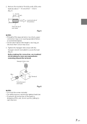
... the hexagon wrench (included) to secure the lead. (Fig. 6) Before making this connection, use the cabling to cover any exposed wire extending beyond the terminal. Remove the insulation from the ends of the wire leads by about 7 - 10 mm (9/32" - 13/32"). (Fig. 5) 7 - 10 mm (9/32" ... tip of wire leads Fig. 5 NOTES: • If length of the unit, do not use insulated shrink tubing to carry the unit. 7-EN 2. Hexagon hole screw Wire Wire Terminal Twist the tip of wire leads Fig. 6 NOTES: • Use only the screws included. • For safety reasons, connect the battery leads last....
... the hexagon wrench (included) to secure the lead. (Fig. 6) Before making this connection, use the cabling to cover any exposed wire extending beyond the terminal. Remove the insulation from the ends of the wire leads by about 7 - 10 mm (9/32" - 13/32"). (Fig. 5) 7 - 10 mm (9/32" ... tip of wire leads Fig. 5 NOTES: • If length of the unit, do not use insulated shrink tubing to carry the unit. 7-EN 2. Hexagon hole screw Wire Wire Terminal Twist the tip of wire leads Fig. 6 NOTES: • Use only the screws included. • For safety reasons, connect the battery leads last....
Owner's Manual (english)
Page 10
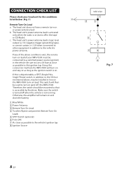
... or CD Mode). Using this is on lead of the above , may be mounted so that is not running. If this connection method, the MRV-V500 will turn on and stay on as long as the ignition switch is logic level output (+) 5V, negative trigger (grounding type), or cannot sustain (+) 12V when connected to other Alpine component's Remote Turn-On Leads SPST Switch (optional) Fuse (3A) As...
... or CD Mode). Using this is on lead of the above , may be mounted so that is not running. If this connection method, the MRV-V500 will turn on and stay on as long as the ignition switch is logic level output (+) 5V, negative trigger (grounding type), or cannot sustain (+) 12V when connected to other Alpine component's Remote Turn-On Leads SPST Switch (optional) Fuse (3A) As...
Owner's Manual (english)
Page 11
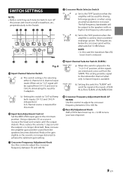
.... Input Gain Adjustment Control Set the MRV-V500 input gain to tune your bass response. 9-EN Reduce the gain slightly so the sound is used for this control to adjust the crossover frequency between 50 to adjust the crossover frequency between 50 and 400 Hz. Input Channel Selector Switch (SUB W.) a) When this control to 400 Hz. of SUB W. (L/R) to CH-3/4, eliminating the need for selecting either 2-channel or 4-channel input mode. b) Set to the "ON" position when the amplifier is no high or...
.... Input Gain Adjustment Control Set the MRV-V500 input gain to tune your bass response. 9-EN Reduce the gain slightly so the sound is used for this control to adjust the crossover frequency between 50 to adjust the crossover frequency between 50 and 400 Hz. Input Channel Selector Switch (SUB W.) a) When this control to 400 Hz. of SUB W. (L/R) to CH-3/4, eliminating the need for selecting either 2-channel or 4-channel input mode. b) Set to the "ON" position when the amplifier is no high or...

Owner's Manual (english)
Page 12
... unit and consult your dealer. The indicator color changes to a normal level. Use the correct power supply voltage. About Power Indicator Power Indicator Fig. 9 Lights up when power is on the unit and verify that the indicator color has changed to blue. Power supply voltage is abnormal. Then turn off the power supply and eliminate the cause. Amplifier circuit is too high. The indicator color changes to blue. 10-EN If it remains red, turn on . Indication color Blue Red (blinking) Red Status Amplifier circuit...
... unit and consult your dealer. The indicator color changes to a normal level. Use the correct power supply voltage. About Power Indicator Power Indicator Fig. 9 Lights up when power is on the unit and verify that the indicator color has changed to blue. Power supply voltage is abnormal. Then turn off the power supply and eliminate the cause. Amplifier circuit is too high. The indicator color changes to blue. 10-EN If it remains red, turn on . Indication color Blue Red (blinking) Red Status Amplifier circuit...

Owner's Manual (english)
Page 13
... Front Speakers Rear Speakers Subwoofer Head Unit, etc. Front Output Rear Output Subwoofer Output RCA Extension Cable (Sold Separately) Y-Adapter (Sold Separately) TYPICAL SYSTEM CONNECTIONS 4 Speaker + 1 Subwoofer System (5-Channel Input) Input Channel Selector Switch Setting CH-3/4 SUB W. 3/4 SUB W. Connecting to the Speaker Level Input System 1 For the "Speaker Level Input System" setting, connecting the Remote Turn-On Lead is not required due to a different Input channel pair. Instead, be sure to connect each pair of inputs to the "REMOTE SENSING" function of the amplifier.
... Front Speakers Rear Speakers Subwoofer Head Unit, etc. Front Output Rear Output Subwoofer Output RCA Extension Cable (Sold Separately) Y-Adapter (Sold Separately) TYPICAL SYSTEM CONNECTIONS 4 Speaker + 1 Subwoofer System (5-Channel Input) Input Channel Selector Switch Setting CH-3/4 SUB W. 3/4 SUB W. Connecting to the Speaker Level Input System 1 For the "Speaker Level Input System" setting, connecting the Remote Turn-On Lead is not required due to a different Input channel pair. Instead, be sure to connect each pair of inputs to the "REMOTE SENSING" function of the amplifier.
Owner's Manual (english)
Page 15
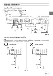
Proper connection Improper connection One signal Fig. 14 One signal 13-EN The Y-adapter is not required if a stereo/mono pair line output is used to drive both inputs of the bridged amp. BRIDGED CONNECTIONS 2 Speaker + 1 Subwoofer System Input Channel Selector Switch Setting CH-3/4 SUB W. 3/4 SUB W. Fig. 13 Important Tips on Bridging an Amplifier NOTE: • Low output will result if only one channel input is used .
Proper connection Improper connection One signal Fig. 14 One signal 13-EN The Y-adapter is not required if a stereo/mono pair line output is used to drive both inputs of the bridged amp. BRIDGED CONNECTIONS 2 Speaker + 1 Subwoofer System Input Channel Selector Switch Setting CH-3/4 SUB W. 3/4 SUB W. Fig. 13 Important Tips on Bridging an Amplifier NOTE: • Low output will result if only one channel input is used .
Owner's Manual (english)
Page 16
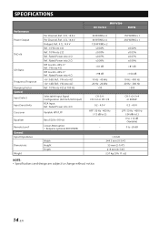
SPECIFICATIONS Performance Power Output THD+N S/N Ratio Frequency Response Damping Factor Control Input Select Input Sensitivity Crossover Equalizer Remote Level General Input Impedance Dimensions Weight Per Channel, Ref.: 4 Ω, 14.4 V Per Channel, Ref.: 2 Ω, 14.4 V Bridged, Ref.: 4 Ω, 14.4 V Ref.: 10 W into 4 Ω Ref.: 10 W into 2 Ω Ref.: Rated Power into 4 Ω Ref.: Rated Power into 2 Ω IHF A-wtd + AES-17 Ref.: 1W into 4 Ω IHF A-wtd + AES-17...
SPECIFICATIONS Performance Power Output THD+N S/N Ratio Frequency Response Damping Factor Control Input Select Input Sensitivity Crossover Equalizer Remote Level General Input Impedance Dimensions Weight Per Channel, Ref.: 4 Ω, 14.4 V Per Channel, Ref.: 2 Ω, 14.4 V Bridged, Ref.: 4 Ω, 14.4 V Ref.: 10 W into 4 Ω Ref.: 10 W into 2 Ω Ref.: Rated Power into 4 Ω Ref.: Rated Power into 2 Ω IHF A-wtd + AES-17 Ref.: 1W into 4 Ω IHF A-wtd + AES-17...

Owner's Manual (espanol)
Page 1
...-6, 3Ga, Pil_dong, Jung_gu, Seoul, Korea Designed by ALPINE Japan Printed in Korea 68-29530Z24-A (Y-A5) M3514555010 FOR CAR USE ONLY/POUR APPLICATION AUTOMOBILE/PARA USO EN AUTOMÓVILES EN MRV-V500 FR 4 CHANNEL + MONO POWER AMPLIFIER ES • OWNER'S MANUAL Please read before using this equipment. • MODE D'EMPLOI Veuillez lire avant d'utiliser cet appareil. • MANUAL DE OPERACIÓN Léalo antes de...
...-6, 3Ga, Pil_dong, Jung_gu, Seoul, Korea Designed by ALPINE Japan Printed in Korea 68-29530Z24-A (Y-A5) M3514555010 FOR CAR USE ONLY/POUR APPLICATION AUTOMOBILE/PARA USO EN AUTOMÓVILES EN MRV-V500 FR 4 CHANNEL + MONO POWER AMPLIFIER ES • OWNER'S MANUAL Please read before using this equipment. • MODE D'EMPLOI Veuillez lire avant d'utiliser cet appareil. • MANUAL DE OPERACIÓN Léalo antes de...

Owner's Manual (french)
Page 1
... 68-29530Z24-A (Y-A5) M3514555010 FOR CAR USE ONLY/POUR APPLICATION AUTOMOBILE/PARA USO EN AUTOMÓVILES EN MRV-V500 FR 4 CHANNEL + MONO POWER AMPLIFIER ES • OWNER'S MANUAL Please read before using this equipment. • MODE D'EMPLOI Veuillez lire avant d'utiliser cet appareil. • MANUAL DE OPERACIÓN Léalo antes de utilizar este equipo. www.alpine.co.uk ALPINE ELECTRONICS FRANCE S.A.R.L. (RCS PONTOISE B 338...
... 68-29530Z24-A (Y-A5) M3514555010 FOR CAR USE ONLY/POUR APPLICATION AUTOMOBILE/PARA USO EN AUTOMÓVILES EN MRV-V500 FR 4 CHANNEL + MONO POWER AMPLIFIER ES • OWNER'S MANUAL Please read before using this equipment. • MODE D'EMPLOI Veuillez lire avant d'utiliser cet appareil. • MANUAL DE OPERACIÓN Léalo antes de utilizar este equipo. www.alpine.co.uk ALPINE ELECTRONICS FRANCE S.A.R.L. (RCS PONTOISE B 338...


