Operating Instructions
Page 3
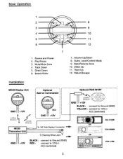
...GND +12V BLACK: connect to Ground (GND) YELLOW: connect to 12V(+): ACC (switched) CDA-9886M CDA-118M 3 ACC (switched) GND +12V 1 I MC20 ~C:::l ce=,.J To 10P Sub Display Connector - . . . Play/Pause 3. Direct Down 6. Subw. Track Down 5. Volume Up/Down 8. GND +12V ... ··· ............ Mute/Mute Zone 4. Source and Power 2. Transceiver Unit To Steering Wheel Jack -... Return/Escape Installation' MC20 Display Unit t_ 2.4GHz Wireless v~ ~, Wireless opti;;;;~i·RUE~M·1·RF····· . Basic Operation 1 2 8 3 ...
...GND +12V BLACK: connect to Ground (GND) YELLOW: connect to 12V(+): ACC (switched) CDA-9886M CDA-118M 3 ACC (switched) GND +12V 1 I MC20 ~C:::l ce=,.J To 10P Sub Display Connector - . . . Play/Pause 3. Direct Down 6. Subw. Track Down 5. Volume Up/Down 8. GND +12V ... ··· ............ Mute/Mute Zone 4. Source and Power 2. Transceiver Unit To Steering Wheel Jack -... Return/Escape Installation' MC20 Display Unit t_ 2.4GHz Wireless v~ ~, Wireless opti;;;;~i·RUE~M·1·RF····· . Basic Operation 1 2 8 3 ...
Operating Instructions
Page 6
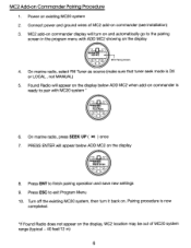
... display 4. Power on Commander Pairing Procedure 1. Connect power and ground wires of MC20 system range (typical - 40 feet/12 m) 6 Turn off the existing MC20 system, then turn on and automatically go to pair with ADD MC2 showing on commander (see Installation) 3. PRESS ENTER will appear on the display below ADD MC2 on commander...
... display 4. Power on Commander Pairing Procedure 1. Connect power and ground wires of MC20 system range (typical - 40 feet/12 m) 6 Turn off the existing MC20 system, then turn on and automatically go to pair with ADD MC2 showing on commander (see Installation) 3. PRESS ENTER will appear on the display below ADD MC2 on commander...


