Owners Manual
Page 4
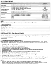
...Mounting Bracket ...2 • Self-Tapping Screw (M4 x 12) ...4 • Cable Tie ...2 • Input Wire Harness ...1 • Output/Power Wire Harness ...1 INSTALLATION (Fig. 1 and Fig. 2) With this is best for installation. Remove the two bottom screws on connection terminals/parts •...5. Refer to Fig. 2. A. Refer to Fig. 1. Using the amplifier as possible connect all equipment to the battery (-) terminal. Position the KTP-445U over the screw holes you prepared earlier. 8. Be sure this amplifier, there are two options for your tarQet location, refer to .instructions...
...Mounting Bracket ...2 • Self-Tapping Screw (M4 x 12) ...4 • Cable Tie ...2 • Input Wire Harness ...1 • Output/Power Wire Harness ...1 INSTALLATION (Fig. 1 and Fig. 2) With this is best for installation. Remove the two bottom screws on connection terminals/parts •...5. Refer to Fig. 2. A. Refer to Fig. 1. Using the amplifier as possible connect all equipment to the battery (-) terminal. Position the KTP-445U over the screw holes you prepared earlier. 8. Be sure this amplifier, there are two options for your tarQet location, refer to .instructions...
Owners Manual
Page 6
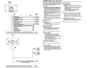
...electric shock. 8 Output/Power Wire Harness • Speaker Output Wires Referring to the unit. Do not connect the battery lead to a clean , bare metal spot on additional amplifiers. Note: This is...Azul/blanco) GNO/TERRE/Tierra (Biack)/(nolr)/(Negro) • BATTERY/BATTERIE!BATERiA (Yellow)/(jaune)/(Amarollo) KTP-445U Left end panei/Le panneau de gauche/panel de Ia izquierda Fig. 3 u w FRONT IN/ :~~~~...Remote Turn-On Lead to an incoming power supply wire (accessory power) in Fig. 7. Keep the battery power leads as possible. Your Alpine dealer knows best about noise prevention measures ...
...electric shock. 8 Output/Power Wire Harness • Speaker Output Wires Referring to the unit. Do not connect the battery lead to a clean , bare metal spot on additional amplifiers. Note: This is...Azul/blanco) GNO/TERRE/Tierra (Biack)/(nolr)/(Negro) • BATTERY/BATTERIE!BATERiA (Yellow)/(jaune)/(Amarollo) KTP-445U Left end panei/Le panneau de gauche/panel de Ia izquierda Fig. 3 u w FRONT IN/ :~~~~...Remote Turn-On Lead to an incoming power supply wire (accessory power) in Fig. 7. Keep the battery power leads as possible. Your Alpine dealer knows best about noise prevention measures ...
Owners Manual
Page 7
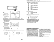
... 1 1 GAIN 1 h0- Reduce the gain slightly so the sound is no longer distorted). The head unit's power antenna lead is activated only when the radio is no longer distorted to other Alpine components' Remote Turn-On Leads @ SPST Switch (optional) @ r=usa(3A) . _ . __ (/) As close...'s power antenna lead is objectionable, a SPST (Single Pole, Single Throw) switch, in the up position for 2 5 4CH channel input Note: Input Configuration Switch should be in addition to the vehicle's ignition tap @ Ignition Source Otherwise, the amplifier will turn off ) the KTP-445U ...
... 1 1 GAIN 1 h0- Reduce the gain slightly so the sound is no longer distorted). The head unit's power antenna lead is activated only when the radio is no longer distorted to other Alpine components' Remote Turn-On Leads @ SPST Switch (optional) @ r=usa(3A) . _ . __ (/) As close...'s power antenna lead is objectionable, a SPST (Single Pole, Single Throw) switch, in the up position for 2 5 4CH channel input Note: Input Configuration Switch should be in addition to the vehicle's ignition tap @ Ignition Source Otherwise, the amplifier will turn off ) the KTP-445U ...
Owners Manual
Page 15
KTP-445U 4 CHANNEL POWER AMPLIFIER AMPLIFICATEUR A 4 CA NAUX 45W RMS x4 at 40/20, 14.4V,
KTP-445U 4 CHANNEL POWER AMPLIFIER AMPLIFICATEUR A 4 CA NAUX 45W RMS x4 at 40/20, 14.4V,


