Owners Manual
Page 3
...About Operation in Calibration Mode 30 Performing Calibration 31 Information Specifications 35 In Case of the Rearview Camera System 17 Mounting the Rearview Camera ...17 1. Installing the Buzzer 20 4. ENGLISH Contents Operating Instructions WARNING DANGER 2 WARNING 2 CAUTION 3 NOTICE 4 Feature About Object Detection Function 5 Cautions Regarding Object... from connected products 15 Changing the Rear Image Configuration 16 Adjusting Alarm Volume 16 Adjusting Detection Sensitivity.....16 Installation and Connections Installation of Difficulty 35 1-EN Preparation 17 2.
...About Operation in Calibration Mode 30 Performing Calibration 31 Information Specifications 35 In Case of the Rearview Camera System 17 Mounting the Rearview Camera ...17 1. Installing the Buzzer 20 4. ENGLISH Contents Operating Instructions WARNING DANGER 2 WARNING 2 CAUTION 3 NOTICE 4 Feature About Object Detection Function 5 Cautions Regarding Object... from connected products 15 Changing the Rear Image Configuration 16 Adjusting Alarm Volume 16 Adjusting Detection Sensitivity.....16 Installation and Connections Installation of Difficulty 35 1-EN Preparation 17 2.
Owners Manual
Page 4
...SYSTEM, THE DRIVER MUST VISUALLY CHECK ACTUAL CONDITIONS AROUND THE VEHICLE. The Object detection function assists the driver in fire or electric shock. WHEN INSTALLING CAMERA AND/OR OBJECT SENSOR, BE SURE TO USE SPECIFIC VEHICLE CALIBRATION KIT OTHERWISE IT WILL NOT ACCURATELY DISPLAY IMAGES. DO NOT PROCEED TO...from very dark to very bright light and vice versa such as headlamp or bright sunlight • moving from looking ahead of the camera. WHEN INSTALLING OR CHECKING A CAMERA AND/OR OBJECT SENSOR, DO SO AFTER PARKING THE CAR IN A LEVEL, SAFE PLACE, TURNING OFF THE ENGINE, AND APPLYING...
...SYSTEM, THE DRIVER MUST VISUALLY CHECK ACTUAL CONDITIONS AROUND THE VEHICLE. The Object detection function assists the driver in fire or electric shock. WHEN INSTALLING CAMERA AND/OR OBJECT SENSOR, BE SURE TO USE SPECIFIC VEHICLE CALIBRATION KIT OTHERWISE IT WILL NOT ACCURATELY DISPLAY IMAGES. DO NOT PROCEED TO...from very dark to very bright light and vice versa such as headlamp or bright sunlight • moving from looking ahead of the camera. WHEN INSTALLING OR CHECKING A CAMERA AND/OR OBJECT SENSOR, DO SO AFTER PARKING THE CAR IN A LEVEL, SAFE PLACE, TURNING OFF THE ENGINE, AND APPLYING...
Owners Manual
Page 5
... may result in fire, electric shock or other than its detection function will exceed the current carrying capacity of differences in the chassis for installation, take such precautions may result in an accident. Warnings may not always be aware of the wire and result in place. MAKE THE...accidents, injury, or damage to the unit and/or the vehicle. DO NOT INSTALL IN LOCATIONS WHICH MIGHT HINDER VEHICLE OPERATION, SUCH AS THE STEERING WHEEL OR SHIFT LEVER. and results in doubt, consult your Alpine dealer. It must be heard due to do so may result in injury. ...
... may result in fire, electric shock or other than its detection function will exceed the current carrying capacity of differences in the chassis for installation, take such precautions may result in an accident. Warnings may not always be aware of the wire and result in place. MAKE THE...accidents, injury, or damage to the unit and/or the vehicle. DO NOT INSTALL IN LOCATIONS WHICH MIGHT HINDER VEHICLE OPERATION, SUCH AS THE STEERING WHEEL OR SHIFT LEVER. and results in doubt, consult your Alpine dealer. It must be heard due to do so may result in injury. ...
Owners Manual
Page 6
... this product to your HCE-C300R. Do not connect it to have the work done. The wiring and installation of the factory installed components (e.g. Route the cables and wiring away from the (-) battery post before installing your authorized Alpine dealer or the nearest Alpine Service Centre for the ... the camera is reinstalled or when the vehicle is a dedicated product. HAVE THE WIRING AND INSTALLATION DONE BY EXPERTS. on the screen or malfunction. When connecting the HCE-C300R to install the camera. It is recommended to use a mobile phone and wireless device near the camera...
... this product to your HCE-C300R. Do not connect it to have the work done. The wiring and installation of the factory installed components (e.g. Route the cables and wiring away from the (-) battery post before installing your authorized Alpine dealer or the nearest Alpine Service Centre for the ... the camera is reinstalled or when the vehicle is a dedicated product. HAVE THE WIRING AND INSTALLATION DONE BY EXPERTS. on the screen or malfunction. When connecting the HCE-C300R to install the camera. It is recommended to use a mobile phone and wireless device near the camera...
Owners Manual
Page 7
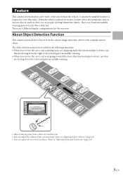
... gives an audible warning. Beep Beep Beep • Objects moving behind the vehicle. Feature This camera system displays a live video of the warning beeps. A separately installed monitor is useful in reverse, besides video, the system also detects various objects (such as other cars or people) moving away from the camera image...
... gives an audible warning. Beep Beep Beep • Objects moving behind the vehicle. Feature This camera system displays a live video of the warning beeps. A separately installed monitor is useful in reverse, besides video, the system also detects various objects (such as other cars or people) moving away from the camera image...
Owners Manual
Page 15
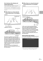
... surface Under the following conditions, errors are produced between the display guidelines and the actual road surface. (The illustrations represent a case when the camera is installed in the standard position.) e When there is a steep upward slope behind the car (example) Actual distance e When there is a steep downward slope behind the car...
... surface Under the following conditions, errors are produced between the display guidelines and the actual road surface. (The illustrations represent a case when the camera is installed in the standard position.) e When there is a steep upward slope behind the car (example) Actual distance e When there is a steep downward slope behind the car...

Owners Manual
Page 16
For details on the screen if the system has not been calibrated. 14-EN This data is necessary to "Calibration" (page 26). • A message appears on how to configure the calibration settings, refer to configure the guidance and install data. About Calibration In order to effectively identify approaching objects, it is entered during the Calibration mode and ensures the most consistent detection results.
For details on the screen if the system has not been calibrated. 14-EN This data is necessary to "Calibration" (page 26). • A message appears on how to configure the calibration settings, refer to configure the guidance and install data. About Calibration In order to effectively identify approaching objects, it is entered during the Calibration mode and ensures the most consistent detection results.
Owners Manual
Page 17
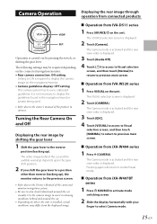
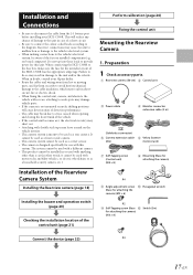
... mode. It is not necessary to display the guidelines found in showing conditions behind and around the car. • Depending on where the unit is installed, actual conditions may be required depending on the connected navigation/monitor. • Rear camera connection: ON setting Setting to ON is carried out by shifting...
... mode. It is not necessary to display the guidelines found in showing conditions behind and around the car. • Depending on where the unit is installed, actual conditions may be required depending on the connected navigation/monitor. • Rear camera connection: ON setting Setting to ON is carried out by shifting...
Owners Manual
Page 19
...use with double stick tape may leave a mark on -board computer). When in doubt, consult your Alpine dealer. • Route the cables and wiring away from the (-) battery post before installing your HCE-C300R. Do not tap into these leads to provide power for attaching the camera) (M3 × 8)...unit in case of the HCE-C300R has the appropriate amperage. This will cause deterioration of detection performance. • The cable may short out. • Attaching with this unit. The system cannot be used with a different camera. • This product cannot be installed in or used with ...
...use with double stick tape may leave a mark on -board computer). When in doubt, consult your Alpine dealer. • Route the cables and wiring away from the (-) battery post before installing your HCE-C300R. Do not tap into these leads to provide power for attaching the camera) (M3 × 8)...unit in case of the HCE-C300R has the appropriate amperage. This will cause deterioration of detection performance. • The cable may short out. • Attaching with this unit. The system cannot be used with a different camera. • This product cannot be installed in or used with ...
Owners Manual
Page 20
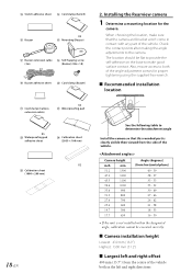
... - 57 35 - 55 33 - 52 30 - 49 27 - 46 24 - 42 21 - 38 18 - 33 16 - 30 • If the unit is not installed within the designated angle, calibration cannot be flat to provide the self-adhesive on the base to the camera. M Switch adhesive sheet N Cord clamp (Switch... sheet (1000 × 200 mm) 18-EN 2. Also, ensure access to determine the attachment angle Install the camera so that the camera and bracket won't come in the left and right directions Installing the Rearview camera 1 Determine a mounting location for proper tightening using the supplied hex wrench. Camera height inch...
... - 57 35 - 55 33 - 52 30 - 49 27 - 46 24 - 42 21 - 38 18 - 33 16 - 30 • If the unit is not installed within the designated angle, calibration cannot be flat to provide the self-adhesive on the base to the camera. M Switch adhesive sheet N Cord clamp (Switch... sheet (1000 × 200 mm) 18-EN 2. Also, ensure access to determine the attachment angle Install the camera so that the camera and bracket won't come in the left and right directions Installing the Rearview camera 1 Determine a mounting location for proper tightening using the supplied hex wrench. Camera height inch...

Owners Manual
Page 21
... camera near the reverse lamp. • If any part of the vehicle body blocks the camera coverage area, detection of that the ALPINE logo of the camera is facing up paint as possible to ensure the detection range of 180°. • Provide enough clearance for ..., etc. (3) Attach the camera to the mounting bracket H with the waterproof pad adhesive sheet W, and secure any hinges. • The cable should be possible. 2 Installing the camera and the camera mounting bracket to the car. e Attaching the Camera Reverse In Camera cable Angle adjustment screw Make sure that area will...
... camera near the reverse lamp. • If any part of the vehicle body blocks the camera coverage area, detection of that the ALPINE logo of the camera is facing up paint as possible to ensure the detection range of 180°. • Provide enough clearance for ..., etc. (3) Attach the camera to the mounting bracket H with the waterproof pad adhesive sheet W, and secure any hinges. • The cable should be possible. 2 Installing the camera and the camera mounting bracket to the car. e Attaching the Camera Reverse In Camera cable Angle adjustment screw Make sure that area will...

Owners Manual
Page 22
... one side, and apply it to the desired location in the car (under a seat, etc.). e Attaching with the supplied self-tapping screw R. Do not install in the desired location. Attach the supplied switch adhesive sheet M. If necessary, secure the cable with the supplied cord clamp T. Do not place anything within...with the supplied cord clamp T. 20-EN Peel off the protective sheet, and apply it to avoid water drops on the other protective sheet and install in areas that the cable feed opening is closed off the other side and apply to the back of the switch, then peel off , ...
... one side, and apply it to the desired location in the car (under a seat, etc.). e Attaching with the supplied self-tapping screw R. Do not install in the desired location. Attach the supplied switch adhesive sheet M. If necessary, secure the cable with the supplied cord clamp T. Do not place anything within...with the supplied cord clamp T. 20-EN Peel off the protective sheet, and apply it to avoid water drops on the other protective sheet and install in areas that the cable feed opening is closed off the other side and apply to the back of the switch, then peel off , ...

Owners Manual
Page 23
... unit with the self-tapping screw G in an area on the rear of the control unit B. Installing the Control Unit 1 Attach the control unit B with Velcro fastener (1) Attach the Velcro fastener (hard side) F to install the control unit on the bottom of the unit undersurface where the label is recommended to the...
... unit with the self-tapping screw G in an area on the rear of the control unit B. Installing the Control Unit 1 Attach the control unit B with Velcro fastener (1) Attach the Velcro fastener (hard side) F to install the control unit on the bottom of the unit undersurface where the label is recommended to the...

Owners Manual
Page 27
Also check for damage from sharp edges or protrusions. Make sure the unit is operating correctly by moving parts such as the brake lamps, etc., work correctly. 25-EN Make sure leads are not pinched by referring to "2. Installing the Rearview camera." (page 18) 2 Connect the battery (-) terminal. 3 Turn on the engine key. Refer to the Owner's Manual. 4 Make sure all factory components such as the seat rail, etc. Confirmation 1 Securing leads, etc.
Also check for damage from sharp edges or protrusions. Make sure the unit is operating correctly by moving parts such as the brake lamps, etc., work correctly. 25-EN Make sure leads are not pinched by referring to "2. Installing the Rearview camera." (page 18) 2 Connect the battery (-) terminal. 3 Turn on the engine key. Refer to the Owner's Manual. 4 Make sure all factory components such as the seat rail, etc. Confirmation 1 Securing leads, etc.
Owners Manual
Page 28
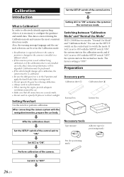
...without being calibrated, or if the calibration sheet is necessary to "OFF". 26-EN Switching between "Calibration Mode" and "Normal Use Mode" HCE-C300R has two modes: "Normal Use Mode" and "Calibration Mode." The factory setting is Calibration? Preparation Accessory parts Calibration sheet A Calibration sheet B...camera position is changed or the camera is set to "ON" activates the system in the normal use mode. If ACC is installed in direct sunlight. Necessary tools Tape measure Adhesive tape (for positioning mark) Pen (for positioning mark) Perform calibration of the ...
...without being calibrated, or if the calibration sheet is necessary to "OFF". 26-EN Switching between "Calibration Mode" and "Normal Use Mode" HCE-C300R has two modes: "Normal Use Mode" and "Calibration Mode." The factory setting is Calibration? Preparation Accessory parts Calibration sheet A Calibration sheet B...camera position is changed or the camera is set to "ON" activates the system in the normal use mode. If ACC is installed in direct sunlight. Necessary tools Tape measure Adhesive tape (for positioning mark) Pen (for positioning mark) Perform calibration of the ...

Owners Manual
Page 29
... that it aligns with heavy items after calibration. Necessary space for any unbalance. Affixing the calibration sheets Affix the calibration sheets and measure the camera installation location. 1 Using calibration sheet B, draw a centre line with a marker or pen on the side of the interior box. (1) Place the interior box on the interior...
... that it aligns with heavy items after calibration. Necessary space for any unbalance. Affixing the calibration sheets Affix the calibration sheets and measure the camera installation location. 1 Using calibration sheet B, draw a centre line with a marker or pen on the side of the interior box. (1) Place the interior box on the interior...

Owners Manual
Page 31
... the sheets for the area directly underneath the bumper and the sheet edges, and make sure they are within ±5 cm (1.97"). 3 Measure the camera installation location (Depth, Height, Offset). (1) Stack the external box and internal box and place them so they are up straight, and affix with the inside of...
... the sheets for the area directly underneath the bumper and the sheet edges, and make sure they are within ±5 cm (1.97"). 3 Measure the camera installation location (Depth, Height, Offset). (1) Stack the external box and internal box and place them so they are up straight, and affix with the inside of...
Owners Manual
Page 33
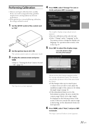
...; Select "Change" under "Language" in the Top menu screen to execute. The Graphic display range adjust screen appears. • Execute calibration at all, adjust the installation angle of the control unit to "ON." 2 Set the ignition key to ACC ON. Line with which to fit within the orange adjustment frame. to...
...; Select "Change" under "Language" in the Top menu screen to execute. The Graphic display range adjust screen appears. • Execute calibration at all, adjust the installation angle of the control unit to "ON." 2 Set the ignition key to ACC ON. Line with which to fit within the orange adjustment frame. to...

Owners Manual
Page 37
Turn the ignition key to OFF and then set to OFF. Check the installation status, and check screws for approximately 1 minute and then turn the ignition key to ON again. • The camera image is not normal. (Images other ... . Check whether the connection is not a malfunction. Connect the reverse signal line while referring to the camera input of the connected product. No fuse is installed, or Install a fuse, or replace a there is not connected to the owner's manual of the connected product.
Turn the ignition key to OFF and then set to OFF. Check the installation status, and check screws for approximately 1 minute and then turn the ignition key to ON again. • The camera image is not normal. (Images other ... . Check whether the connection is not a malfunction. Connect the reverse signal line while referring to the camera input of the connected product. No fuse is installed, or Install a fuse, or replace a there is not connected to the owner's manual of the connected product.

