Owners Manual
Page 3
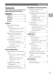
...the calibration sheets.......27 About Operation in Calibration Mode 30 Performing Calibration 31 Information Specifications 35 In Case of the Rearview Camera System 17 Mounting the Rearview Camera ...17 1. Installing the Buzzer 20 4. ENGLISH Contents Operating Instructions WARNING DANGER 2 WARNING 2 CAUTION 3 NOTICE 4 ...Flowchart 26 Switching between the display and actual road surface 13 Warning Message Displays 13 About Calibration 14 Camera Operation Turning the Rear Camera On and Off 15 Displaying the rear image by shifting the gear lever 15 Displaying the rear image...
...the calibration sheets.......27 About Operation in Calibration Mode 30 Performing Calibration 31 Information Specifications 35 In Case of the Rearview Camera System 17 Mounting the Rearview Camera ...17 1. Installing the Buzzer 20 4. ENGLISH Contents Operating Instructions WARNING DANGER 2 WARNING 2 CAUTION 3 NOTICE 4 ...Flowchart 26 Switching between the display and actual road surface 13 Warning Message Displays 13 About Calibration 14 Camera Operation Turning the Rear Camera On and Off 15 Displaying the rear image by shifting the gear lever 15 Displaying the rear image...
Owners Manual
Page 4
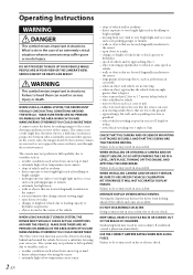
...snow, fog or mud • dense exhaust fumes obscuring the sensor • extremely high or low temperatures near camera • slope of the camera. WARNING This symbol means important instructions. DO NOT DISASSEMBLE OR ALTER. SERIOUS INJURY OR DEATH CAN RESULT. Operating ...• approaching a flat wall, such as what appears on the screen. If swallowed, consult a physician immediately. WHEN USING A CAMERA SYSTEM, THE DRIVER MUST VISUALLY CHECK ACTUAL CONDITIONS AROUND THE VEHICLE. The Object detection function assists the driver in checking behind vehicle &#...
...snow, fog or mud • dense exhaust fumes obscuring the sensor • extremely high or low temperatures near camera • slope of the camera. WARNING This symbol means important instructions. DO NOT DISASSEMBLE OR ALTER. SERIOUS INJURY OR DEATH CAN RESULT. Operating ...• approaching a flat wall, such as what appears on the screen. If swallowed, consult a physician immediately. WHEN USING A CAMERA SYSTEM, THE DRIVER MUST VISUALLY CHECK ACTUAL CONDITIONS AROUND THE VEHICLE. The Object detection function assists the driver in checking behind vehicle &#...
Owners Manual
Page 5
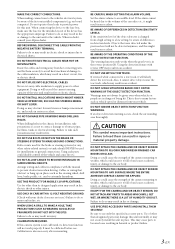
... This may not securely install the unit in an accident. DO NOT SPLICE INTO ELECTRICAL CABLES. and results in doubt, consult your Alpine dealer. DO NOT USE BOLTS OR NUTS IN THE BRAKE OR STEERING SYSTEMS TO MAKE GROUND CONNECTIONS. Arrange wiring and cables in compliance ... obstructions when driving. If the alarm cannot be detected anymore, and this unit internally or may cause parts to the volume of the camera mounting to contact, damage or obstruct pipes, fuel lines, tanks or electrical wiring. CAUTION This symbol means important instructions. When making connections...
... This may not securely install the unit in an accident. DO NOT SPLICE INTO ELECTRICAL CABLES. and results in doubt, consult your Alpine dealer. DO NOT USE BOLTS OR NUTS IN THE BRAKE OR STEERING SYSTEMS TO MAKE GROUND CONNECTIONS. Arrange wiring and cables in compliance ... obstructions when driving. If the alarm cannot be detected anymore, and this unit internally or may cause parts to the volume of the camera mounting to contact, damage or obstruct pipes, fuel lines, tanks or electrical wiring. CAUTION This symbol means important instructions. When making connections...
Owners Manual
Page 6
... safety, always contact the dealer where you purchased this camera system is a enough space to be able to install the camera. If possible, install the camera in the centre of the bumper or other cameras. When connecting the HCE-C300R to the wiring. Route the cables and wiring away ...be provided. ARRANGE THE WIRING SO IT IS NOT CRIMPED OR PINCHED BY A SHARP METAL EDGE. Double-check your authorized Alpine dealer or the nearest Alpine Service Centre for the intended circuit of the factory installed components (e.g. This location must be able to attach the device,...
... safety, always contact the dealer where you purchased this camera system is a enough space to be able to install the camera. If possible, install the camera in the centre of the bumper or other cameras. When connecting the HCE-C300R to the wiring. Route the cables and wiring away ...be provided. ARRANGE THE WIRING SO IT IS NOT CRIMPED OR PINCHED BY A SHARP METAL EDGE. Double-check your authorized Alpine dealer or the nearest Alpine Service Centre for the intended circuit of the factory installed components (e.g. This location must be able to attach the device,...
Owners Manual
Page 7
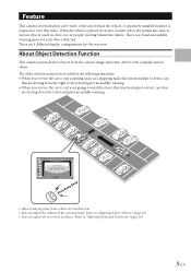
... vehicle is useful in reverse, besides video, the system also detects various objects (such as other cars or people) moving away from the camera image and warns drivers with a display and an alarm. Beep Beep Beep • Objects moving behind the vehicle. Feature This... live video of the warning beeps. A separately installed monitor is a visual and audible warning given for the rear view. About Object Detection Function This camera system detects objects from vehicle are not detected. • You can adjust the sensitivity to detect cars that are driving down the street and gives...
... vehicle is useful in reverse, besides video, the system also detects various objects (such as other cars or people) moving away from the camera image and warns drivers with a display and an alarm. Beep Beep Beep • Objects moving behind the vehicle. Feature This... live video of the warning beeps. A separately installed monitor is a visual and audible warning given for the rear view. About Object Detection Function This camera system detects objects from vehicle are not detected. • You can adjust the sensitivity to detect cars that are driving down the street and gives...

Owners Manual
Page 8
...the vehicle and objects are difficult to help the driver make safe driving decisions. Be sure to detect moving objects. This system uses the camera's image to perform a visual check. • Road paint (for example, crosswalks), tire chocks, curbstones • Thin objects (for ...for the following objects. We are detectable. In other cases, no moving vehicles are visible in contact with your vehicle. • This camera distorts object size and distance from directly behind the vehicle • Objects approaching from a slope Motionless objects are motionless - e Object ...
...the vehicle and objects are difficult to help the driver make safe driving decisions. Be sure to detect moving objects. This system uses the camera's image to perform a visual check. • Road paint (for example, crosswalks), tire chocks, curbstones • Thin objects (for ...for the following objects. We are detectable. In other cases, no moving vehicles are visible in contact with your vehicle. • This camera distorts object size and distance from directly behind the vehicle • Objects approaching from a slope Motionless objects are motionless - e Object ...

Owners Manual
Page 9
...objects when the vehicle moves very slowly • Object moving near the vehicle or its own hazard lamps flashing. • When light hits the camera directly (If a license plate lamp has been customized to be brighter than normal, etc.) • If the vehicle is closer to the ...shorter Your vehicle 2.5 mph (4 km/h) Arrival time is interrupted by the vehicle's body • When tires are recognized as high priority from the camera's scope because of exhaust gases, rain, fog, snow, or mud • False detection because of Warning Objects If multiple objects are selected according...
...objects when the vehicle moves very slowly • Object moving near the vehicle or its own hazard lamps flashing. • When light hits the camera directly (If a license plate lamp has been customized to be brighter than normal, etc.) • If the vehicle is closer to the ...shorter Your vehicle 2.5 mph (4 km/h) Arrival time is interrupted by the vehicle's body • When tires are recognized as high priority from the camera's scope because of exhaust gases, rain, fog, snow, or mud • False detection because of Warning Objects If multiple objects are selected according...

Owners Manual
Page 10
...No warning also occurs when the object moves away from a side. An alarm also starts to sound. There may be detected. • Because this camera system detects objects based on a Panorama View image, warnings can occur even if an object does not show on the screen, a small box appears...warning ends when the object comes directly behind the vehicle. The system boxes off the object in a crowd of the screen, indicating that enters the camera's view. e Rear View Display Indications A triangle mark appears on the leftmost or rightmost side of people, the outer frame light will not be...
...No warning also occurs when the object moves away from a side. An alarm also starts to sound. There may be detected. • Because this camera system detects objects based on a Panorama View image, warnings can occur even if an object does not show on the screen, a small box appears...warning ends when the object comes directly behind the vehicle. The system boxes off the object in a crowd of the screen, indicating that enters the camera's view. e Rear View Display Indications A triangle mark appears on the leftmost or rightmost side of people, the outer frame light will not be...

Owners Manual
Page 12
... system detects an object only when the gear lever is in the reverse position (R). • If a rear camera image is displayed without placing the gear lever in the reverse position (when you call a rear camera image from the menu screen for example), object detection is being displayed. • The moving or stationary.
... system detects an object only when the gear lever is in the reverse position (R). • If a rear camera image is displayed without placing the gear lever in the reverse position (when you call a rear camera image from the menu screen for example), object detection is being displayed. • The moving or stationary.
Owners Manual
Page 13
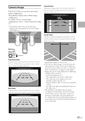
... the lower section of the display. Ground View Panorama View: Displays a general perspective of centre. can select and switch image configurations. Camera Image With HCE-C300R, you want to view a wider than normal area behind the car. In the dark (nighttime, etc.) - Corner View: Displays ...a divided image left and right directional view. The camera has water droplets on or around the camera. - Foreign substances (dirt, etc.) are for example....
... the lower section of the display. Ground View Panorama View: Displays a general perspective of centre. can select and switch image configurations. Camera Image With HCE-C300R, you want to view a wider than normal area behind the car. In the dark (nighttime, etc.) - Corner View: Displays ...a divided image left and right directional view. The camera has water droplets on or around the camera. - Foreign substances (dirt, etc.) are for example....
Owners Manual
Page 14
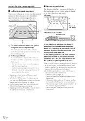
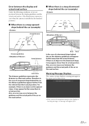
...• The lines do not move in reverse gear, the monitor switches to the right or left. When sunlight or headlights directly strike the camera lens. 12-EN B Distance guidelines The horizontal lines represent the distance from the rear of the car (from the actual surroundings. • ... determining distances to help in order of proximity. Objects near both ends of the bumper and objects under the bumper may deviate to the rear camera view. This is high or low. - When foreign bodies (such as rainy weather, etc.). - e Distance guidelines The distance guidelines represents the...
...• The lines do not move in reverse gear, the monitor switches to the right or left. When sunlight or headlights directly strike the camera lens. 12-EN B Distance guidelines The horizontal lines represent the distance from the rear of the car (from the actual surroundings. • ... determining distances to help in order of proximity. Objects near both ends of the bumper and objects under the bumper may deviate to the rear camera view. This is high or low. - When foreign bodies (such as rainy weather, etc.). - e Distance guidelines The distance guidelines represents the...
Owners Manual
Page 15
... slope, it may appear closer than their actual position. If there is an object on the road surface. Warning Message Displays This camera system displays warning messages in the upper part of the car on the downward slope, it may appear further away than the actual distance.... Also, an error may occur between the display guidelines and the actual road surface. (The illustrations represent a case when the camera is installed in the case of a downward slope behind the car, the distance guidelines appear further from the vehicle than its actual position. ...
... slope, it may appear closer than their actual position. If there is an object on the road surface. Warning Message Displays This camera system displays warning messages in the upper part of the car on the downward slope, it may appear further away than the actual distance.... Also, an error may occur between the display guidelines and the actual road surface. (The illustrations represent a case when the camera is installed in the case of a downward slope behind the car, the distance guidelines appear further from the vehicle than its actual position. ...
Owners Manual
Page 17
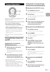
...around the car. • Depending on where the unit is installed, actual conditions may be required depending on the connected navigation/monitor. • Rear camera connection: ON setting Setting to ON is displayed. 3 Touch [ESC]. 4 Touch [VISUAL] to access to Visual selection screen, and then touch [NORMAL...] to return to select Camera mode. 15-EN e Operation from IVA-W520 series 1 Press VISUAL on the unit. Pressing again will return to connect. It is displayed. 3 Touch ...
...around the car. • Depending on where the unit is installed, actual conditions may be required depending on the connected navigation/monitor. • Rear camera connection: ON setting Setting to ON is displayed. 3 Touch [ESC]. 4 Touch [VISUAL] to access to Visual selection screen, and then touch [NORMAL...] to return to select Camera mode. 15-EN e Operation from IVA-W520 series 1 Press VISUAL on the unit. Pressing again will return to connect. It is displayed. 3 Touch ...
Owners Manual
Page 19
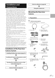
... screw J Hexagonal wrench (Base for attaching the camera) (M3 × 6) X2 K Self-Tapping screw (Base L Switch (3m) for this system. When in other than a car (in doubt, consult your Alpine dealer. • Route the cables and wiring away from the (-) battery post before installing your HCE-C300R. This will reduce any chance of damage...
... screw J Hexagonal wrench (Base for attaching the camera) (M3 × 6) X2 K Self-Tapping screw (Base L Switch (3m) for this system. When in other than a car (in doubt, consult your Alpine dealer. • Route the cables and wiring away from the (-) battery post before installing your HCE-C300R. This will reduce any chance of damage...
Owners Manual
Page 20
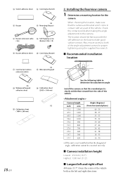
...table to both in contact with any part of the vehicle. Also, ensure access to determine the attachment angle Install the camera so that the camera and bracket won't come in the left and right offset 400 mm (15.7") from the centre of the vehicle both... P Mounting (Buzzer) Q Buzzer extension cable R Self-Tapping screw (3m) (Buzzer) (M6 × 10) S Buzzer adhesive sheet T Cord clamp (Buzzer) U Cord clamp (Camera extension cable) X3 V Waterproofing pad X5 W Waterproofing pad adhesive sheet X Calibration sheet (2039 × 100 mm) X2 Y Calibration sheet (1000 × 200 mm) 18-EN...
...table to both in contact with any part of the vehicle. Also, ensure access to determine the attachment angle Install the camera so that the camera and bracket won't come in the left and right offset 400 mm (15.7") from the centre of the vehicle both... P Mounting (Buzzer) Q Buzzer extension cable R Self-Tapping screw (3m) (Buzzer) (M6 × 10) S Buzzer adhesive sheet T Cord clamp (Buzzer) U Cord clamp (Camera extension cable) X3 V Waterproofing pad X5 W Waterproofing pad adhesive sheet X Calibration sheet (2039 × 100 mm) X2 Y Calibration sheet (1000 × 200 mm) 18-EN...

Owners Manual
Page 21
... making contact with the waterproof pad adhesive sheet W, and secure any slack cable around the waterproof pad V using the cord clamp U. e Making holes for the camera cable (1) Drill a 13 mm (1/2") hole at 90° to the rear bumper. e Depth A maximum of 300 mm (11.8") from the tip of the rear... bumper (wipers, rear-side racks, etc.). • Do not install the camera near the reverse lamp. • If any part of the vehicle body blocks the camera coverage area, detection of that the ALPINE logo of the camera is facing up paint as possible to ensure the detection range of car hinges and...
... making contact with the waterproof pad adhesive sheet W, and secure any slack cable around the waterproof pad V using the cord clamp U. e Making holes for the camera cable (1) Drill a 13 mm (1/2") hole at 90° to the rear bumper. e Depth A maximum of 300 mm (11.8") from the tip of the rear... bumper (wipers, rear-side racks, etc.). • Do not install the camera near the reverse lamp. • If any part of the vehicle body blocks the camera coverage area, detection of that the ALPINE logo of the camera is facing up paint as possible to ensure the detection range of car hinges and...

Owners Manual
Page 24
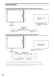
... side of the reverse lamp signal lead of the vehicle To Alpine's Camera Control lead or Reverse lead To Alpine's Alert In lead To Video Input Connector when connecting with the navigation or monitor that has no direct camera input connector To the direct camera input connector of the navigation or monitor Switch (Included) Buzzer...
... side of the reverse lamp signal lead of the vehicle To Alpine's Camera Control lead or Reverse lead To Alpine's Alert In lead To Video Input Connector when connecting with the navigation or monitor that has no direct camera input connector To the direct camera input connector of the navigation or monitor Switch (Included) Buzzer...

Owners Manual
Page 25
... into reverse (R). H Alert Out Lead* Outputs an obstacle detection signal. * Currently not used. Switches the video picture to the direct camera input connector of the navigation or monitor. This is securely fastened using the sheet metal screw provided. K Switch Connector L Buzzer Connector M Rear... Camera Input Connector N SETUP switch (ON/OFF) Use this switch when calibration is turned on or in the accessory position. C Battery Lead ...
... into reverse (R). H Alert Out Lead* Outputs an obstacle detection signal. * Currently not used. Switches the video picture to the direct camera input connector of the navigation or monitor. This is securely fastened using the sheet metal screw provided. K Switch Connector L Buzzer Connector M Rear... Camera Input Connector N SETUP switch (ON/OFF) Use this switch when calibration is turned on or in the accessory position. C Battery Lead ...
Owners Manual
Page 26
...terminals Navigation or monitor (commercial product) Video Output Connector Yellow RCA Extension Cable (Sold Separately) Video Input Connector Orange/Black Camera Control Lead Orange/White Reverse Lead IVA-W520 series, etc. * Use this connection for products which only have a Reverse lead trigger ...for the camera display. • When you route and arrange cables around the vehicle interior, do so as to avoid hot/moving parts. • Connect the cameras by referring carefully to connection instructions or labels. 24-EN
...terminals Navigation or monitor (commercial product) Video Output Connector Yellow RCA Extension Cable (Sold Separately) Video Input Connector Orange/Black Camera Control Lead Orange/White Reverse Lead IVA-W520 series, etc. * Use this connection for products which only have a Reverse lead trigger ...for the camera display. • When you route and arrange cables around the vehicle interior, do so as to avoid hot/moving parts. • Connect the cameras by referring carefully to connection instructions or labels. 24-EN

Owners Manual
Page 27
Installing the Rearview camera." (page 18) 2 Connect the battery (-) terminal. 3 Turn on the engine key. Also check for damage from sharp edges or protrusions. Make sure the unit is operating correctly by moving parts such as the brake lamps, etc., work correctly. 25-EN Make sure leads are not pinched by referring to "2. Refer to the Owner's Manual. 4 Make sure all factory components such as the seat rail, etc. Confirmation 1 Securing leads, etc.
Installing the Rearview camera." (page 18) 2 Connect the battery (-) terminal. 3 Turn on the engine key. Also check for damage from sharp edges or protrusions. Make sure the unit is operating correctly by moving parts such as the brake lamps, etc., work correctly. 25-EN Make sure leads are not pinched by referring to "2. Refer to the Owner's Manual. 4 Make sure all factory components such as the seat rail, etc. Confirmation 1 Securing leads, etc.

