

Owners Manual
Page 1
...• MANUAL DE OPERACIÓN Léalo antes de utilizar este equipo. ® ALPINE ELECTRONICS MARKETING, INC. 1-1-8 Nishi Gotanda, Shinagawa-ku, Tokyo 141-0031, Japan Phone 03-5496-8231 ALPINE ELECTRONICS OF AMERICA, INC. 19145 Gramercy Place, Torrance, California 90501, U.S.A. APDO 133, ...Co., Ltd 127-2 Gamjeon-dong Sasang-gu Busan Korea ALPINE ELECTRONICS OF AUSTRALIA PTY. Phone 0870-33 33 763 ALPINE ELECTRONICS FRANCE S.A.R.L. (RCS PONTOISE B 338 101 280) 98, Rue de la Belle Etoile, Z.I. LTD. R EN RUX-C701 CONTROL FOR PXA-H701 FR MULTIMEDIA MANAGER™ •...
...• MANUAL DE OPERACIÓN Léalo antes de utilizar este equipo. ® ALPINE ELECTRONICS MARKETING, INC. 1-1-8 Nishi Gotanda, Shinagawa-ku, Tokyo 141-0031, Japan Phone 03-5496-8231 ALPINE ELECTRONICS OF AMERICA, INC. 19145 Gramercy Place, Torrance, California 90501, U.S.A. APDO 133, ...Co., Ltd 127-2 Gamjeon-dong Sasang-gu Busan Korea ALPINE ELECTRONICS OF AUSTRALIA PTY. Phone 0870-33 33 763 ALPINE ELECTRONICS FRANCE S.A.R.L. (RCS PONTOISE B 338 101 280) 98, Rue de la Belle Etoile, Z.I. LTD. R EN RUX-C701 CONTROL FOR PXA-H701 FR MULTIMEDIA MANAGER™ •...
Owners Manual
Page 3
Contents Operating Instructions WARNING WARNING 2 CAUTION 3 PRECAUTIONS 3 Operation About the control unit operation 3 Installation and Connections Accessories 4 Installation 5 Basic Connections Diagram 6 Others Specifications 7 LIMITED WARRANTY ENGLISH FR ES DE IT SE 1-EN
Contents Operating Instructions WARNING WARNING 2 CAUTION 3 PRECAUTIONS 3 Operation About the control unit operation 3 Installation and Connections Accessories 4 Installation 5 Basic Connections Diagram 6 Others Specifications 7 LIMITED WARRANTY ENGLISH FR ES DE IT SE 1-EN
Owners Manual
Page 4
.... DO NOT USE BOLTS OR NUTS IN THE BRAKE OR STEERING SYSTEMS TO MAKE GROUND CONNECTIONS. DO NOT INSTALL THE MONITOR NEAR THE ...THE CORRECT CONNECTIONS. If swallowed, consult a physician immediately. If the unit is not installed correctly the air bag may not function correctly and... ELECTRICAL CABLES. Failure to prevent obstructions when driving. USE ONLY IN CARS WITH A 12 VOLT NEGATIVE GROUND. (Check with the manual to ... USE THIS PRODUCT FOR MOBILE 12V APPLICATIONS. Using such parts could disable control of the vehicle and cause an accident. WARNING WARNING This symbol means ...
.... DO NOT USE BOLTS OR NUTS IN THE BRAKE OR STEERING SYSTEMS TO MAKE GROUND CONNECTIONS. DO NOT INSTALL THE MONITOR NEAR THE ...THE CORRECT CONNECTIONS. If swallowed, consult a physician immediately. If the unit is not installed correctly the air bag may not function correctly and... ELECTRICAL CABLES. Failure to prevent obstructions when driving. USE ONLY IN CARS WITH A 12 VOLT NEGATIVE GROUND. (Check with the manual to ... USE THIS PRODUCT FOR MOBILE 12V APPLICATIONS. Using such parts could disable control of the vehicle and cause an accident. WARNING WARNING This symbol means ...
Owners Manual
Page 5
...°C (+14°F) before turning your authorized Alpine dealer or the nearest Alpine Service Center for servicing. Make sure the RUX-C701 will prevent crimping and damage to Maintenance have problems, do so may not securely install the unit in a location subjected to: HAVE THE WIRING ... accessory parts. SE 3-EN Return it to your Alpine dealer or the nearest Alpine Service Station for repairing. For details about the control unit operation, refer to Installation Location the product. Return it to your unit on. This will not be installed in place. ...
...°C (+14°F) before turning your authorized Alpine dealer or the nearest Alpine Service Center for servicing. Make sure the RUX-C701 will prevent crimping and damage to Maintenance have problems, do so may not securely install the unit in a location subjected to: HAVE THE WIRING ... accessory parts. SE 3-EN Return it to your Alpine dealer or the nearest Alpine Service Station for repairing. For details about the control unit operation, refer to Installation Location the product. Return it to your unit on. This will not be installed in place. ...
Owners Manual
Page 6
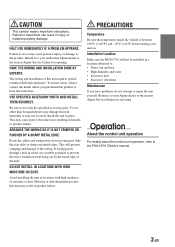
... the control unit. Accessories Display cable Microphone Velcro fastener for mounting control unit SERIAL NUMBER: INSTALLATION DATE: INSTALLATION TECHNICIAN: PLACE OF PURCHASE: Pan head screw Flat head screw (M3 x 5) (M5 x 8) Flush mount To prevent external noise from entering the audio system. • Locate the unit and route the leads at least 10 cm away from the car harness...
... the control unit. Accessories Display cable Microphone Velcro fastener for mounting control unit SERIAL NUMBER: INSTALLATION DATE: INSTALLATION TECHNICIAN: PLACE OF PURCHASE: Pan head screw Flat head screw (M3 x 5) (M5 x 8) Flush mount To prevent external noise from entering the audio system. • Locate the unit and route the leads at least 10 cm away from the car harness...
Owners Manual
Page 7
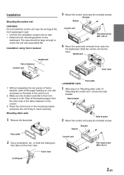
... case 1. Inner case Locking pin Face plate 1 After step 2 on "Mounting other units" of the control unit. 2. The area should be safe. • Determine the mounting position on the control. 3. IT Bracket Spacer Control unit Pan head screw (M3 x 5) x 2 SE 5-EN Without separating the two pieces...paper from moisture or dirt. Mounting other side of the Velcro fastener on the dashboard. Installation Mounting the control unit CAUTION: Do not install the control unit near the air-bag of the front passenger's seat. • Confirm the installation location will be large ...
... case 1. Inner case Locking pin Face plate 1 After step 2 on "Mounting other units" of the control unit. 2. The area should be safe. • Determine the mounting position on the control. 3. IT Bracket Spacer Control unit Pan head screw (M3 x 5) x 2 SE 5-EN Without separating the two pieces...paper from moisture or dirt. Mounting other side of the Velcro fastener on the dashboard. Installation Mounting the control unit CAUTION: Do not install the control unit near the air-bag of the front passenger's seat. • Confirm the installation location will be large ...
Owners Manual
Page 8
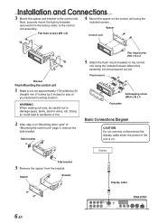
... (R) ANALOG 1 Ai-NET IN CHANGER IN POWER SUPPLY ANALOG 2 ANALOG 3 Installation and Connections 3 Mount the spacer and bracket to the control unit using the included screws. Display Side bracket 3 Remove the spacer from the factory radio, to damage pipes, tanks, electric wires, etc. Next...the bracket. Mount this assembly into the prepared cut -outs, be careful not to the control unit assembly. 4 Mount the spacer on . Spacer Flat head screws (M5 x 8) Control unit Bracket Flush Mounting the control unit 1 Make a cut-out approximately 178 (width) by 50 (height) mm (7 inches...
... (R) ANALOG 1 Ai-NET IN CHANGER IN POWER SUPPLY ANALOG 2 ANALOG 3 Installation and Connections 3 Mount the spacer and bracket to the control unit using the included screws. Display Side bracket 3 Remove the spacer from the factory radio, to damage pipes, tanks, electric wires, etc. Next...the bracket. Mount this assembly into the prepared cut -outs, be careful not to the control unit assembly. 4 Mount the spacer on . Spacer Flat head screws (M5 x 8) Control unit Bracket Flush Mounting the control unit 1 Make a cut-out approximately 178 (width) by 50 (height) mm (7 inches...
Owners Manual
Page 9
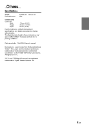
...-D symbol are subject to change without notice. FR ES DE IT SE 7-EN Others Specifications Weight: Illumination color: Control unit 159 g (5 oz) blue Dimensions Control unit Width Height Depth 170 mm (6-3/4") 46 mm (1-13/16") 24 mm (15/16") Due to continuous product improvement..., specifications and design are trademarks of Digital Theater Systems, Inc. The illustrations included in these instructions may appear different from Dolby...
...-D symbol are subject to change without notice. FR ES DE IT SE 7-EN Others Specifications Weight: Illumination color: Control unit 159 g (5 oz) blue Dimensions Control unit Width Height Depth 170 mm (6-3/4") 46 mm (1-13/16") 24 mm (15/16") Due to continuous product improvement..., specifications and design are trademarks of Digital Theater Systems, Inc. The illustrations included in these instructions may appear different from Dolby...


