Getting Started Guide
Page 5
...: 1.Wear an anti-static wrist strap or take other suitable measures to prevent electrostatic discharge when handling this equipment. 2.When connecting this equipment in a residential area is likely to cause interference, in which are cautioned that changes or modifications not expressly ...set out in low-voltage supply system according to correct the interference. For fiber optic connections, you may use 50/125 or 62.5/ 125 micron multimode fiber or 9/125 micron single-mode fiber. Class A This equipment generates, uses, and can radiate radio frequency energy and, if not installed and used...
...: 1.Wear an anti-static wrist strap or take other suitable measures to prevent electrostatic discharge when handling this equipment. 2.When connecting this equipment in a residential area is likely to cause interference, in which are cautioned that changes or modifications not expressly ...set out in low-voltage supply system according to correct the interference. For fiber optic connections, you may use 50/125 or 62.5/ 125 micron multimode fiber or 9/125 micron single-mode fiber. Class A This equipment generates, uses, and can radiate radio frequency energy and, if not installed and used...

Getting Started Guide
Page 7
... Set Specifications 120 Volts UL Listed/CSA Certified Cord Set Minimum 18 AWG Type SVT or SJT three conductor cord Maximum length of 15 feet Parallel blade, grounding type attachment plug rated 15A, 125V 240 Volts (Europe only) Cord Set with...DEVICE powered on . Also, never look at the fiber TX port and fiber cable ends when they are necessary when connecting it to any input voltage within the range marked on the cable) against the following safety information carefully before installing the switch: WARNING: Installation and removal of 0.75 mm2 IEC-320 receptacle Male plug rated...
... Set Specifications 120 Volts UL Listed/CSA Certified Cord Set Minimum 18 AWG Type SVT or SJT three conductor cord Maximum length of 15 feet Parallel blade, grounding type attachment plug rated 15A, 125V 240 Volts (Europe only) Cord Set with...DEVICE powered on . Also, never look at the fiber TX port and fiber cable ends when they are necessary when connecting it to any input voltage within the range marked on the cable) against the following safety information carefully before installing the switch: WARNING: Installation and removal of 0.75 mm2 IEC-320 receptacle Male plug rated...

Getting Started Guide
Page 8
... be of type HO3VVF3GO.75 (minimum). The mains cord must comply with BS1363 (3-pin 13 A) and be powered by disconnecting the power cord from IT† supplies. You can only remove power from the unit by 230 V (2P+T) via an isolation transformer ratio 1:1, with BS1362. The mains cord must be fitted with a 5 A fuse which it is connected also...
... be of type HO3VVF3GO.75 (minimum). The mains cord must comply with BS1363 (3-pin 13 A) and be powered by disconnecting the power cord from IT† supplies. You can only remove power from the unit by 230 V (2P+T) via an isolation transformer ratio 1:1, with BS1362. The mains cord must be fitted with a 5 A fuse which it is connected also...

Getting Started Guide
Page 11
...port when it is powered on the tri-pole power plug to a valid earth ground line to prevent electrostatic discharge when handling this equipment. Les raccordeurs ne sont pas utilisé pour le système téléphonique! When connecting this device. Achtung: Installation... does not contain any serviceable user parts. Installation and removal of a Class 1 Laser Product and are compliant with RJ-45 connectors that conform to transmit signals over fiber optic cable. This switch uses lasers to FCC standards. Use only twisted-pair cables with the requirements of ...
...port when it is powered on the tri-pole power plug to a valid earth ground line to prevent electrostatic discharge when handling this equipment. Les raccordeurs ne sont pas utilisé pour le système téléphonique! When connecting this device. Achtung: Installation... does not contain any serviceable user parts. Installation and removal of a Class 1 Laser Product and are compliant with RJ-45 connectors that conform to transmit signals over fiber optic cable. This switch uses lasers to FCC standards. Use only twisted-pair cables with the requirements of ...

Getting Started Guide
Page 15
... Switch Architecture Network Management Options Description of Hardware 10/100/1000BASE-T Ports SFP Slots Status LEDs Setting the Working Modes Optional Backup Power Supply Power Supply Receptacles Features and Benefits Connectivity Expandability Performance Management Chapter 2: Installing the Switch Selecting a Site Ethernet Cabling Equipment Checklist Package Contents Optional Rack-Mounting Equipment Mounting Rack Mounting Desktop or Shelf Mounting Installing an Optional SFP Transceiver into the Switch Connecting to a Power Source Connecting the BPS to the Switch Installation Instructions...
... Switch Architecture Network Management Options Description of Hardware 10/100/1000BASE-T Ports SFP Slots Status LEDs Setting the Working Modes Optional Backup Power Supply Power Supply Receptacles Features and Benefits Connectivity Expandability Performance Management Chapter 2: Installing the Switch Selecting a Site Ethernet Cabling Equipment Checklist Package Contents Optional Rack-Mounting Equipment Mounting Rack Mounting Desktop or Shelf Mounting Installing an Optional SFP Transceiver into the Switch Connecting to a Power Source Connecting the BPS to the Switch Installation Instructions...
Getting Started Guide
Page 16
Contents 1000 Mbps Gigabit Ethernet Collision Domain 100 Mbps Fast Ethernet Collision Domain 10 Mbps Ethernet Collision Domain Cable Labeling and Connection Records Appendix A: Troubleshooting Diagnosing Switch Indicators Power and Cooling Problems Installation In-Band Access Appendix B: Cables Twisted-Pair Cable and Pin Assignments 10BASE-T/100BASE-TX Pin Assignments 1000BASE-T Pin Assignments Fiber Standards Appendix C: Specifications Compliances Glossary Index 3-24 3-25 3-25 3-26 4-27 4-27 4-27 4-27 4-27 5-29 5-29 5-29 5-30 5-31 6-33 6-36 xvi
Contents 1000 Mbps Gigabit Ethernet Collision Domain 100 Mbps Fast Ethernet Collision Domain 10 Mbps Ethernet Collision Domain Cable Labeling and Connection Records Appendix A: Troubleshooting Diagnosing Switch Indicators Power and Cooling Problems Installation In-Band Access Appendix B: Cables Twisted-Pair Cable and Pin Assignments 10BASE-T/100BASE-TX Pin Assignments 1000BASE-T Pin Assignments Fiber Standards Appendix C: Specifications Compliances Glossary Index 3-24 3-25 3-25 3-26 4-27 4-27 4-27 4-27 4-27 5-29 5-29 5-29 5-30 5-31 6-33 6-36 xvi
Getting Started Guide
Page 21
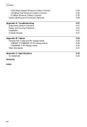
... ports (with SFP or 10/100/1000Base-TX interfaces) and two ports full-duplex Gigabit stacking • OS-LS-6224U - All devices have a management port which is powered by a DC power source rather than an AC. • OS-LS-6248-DC - 48 RJ-45 10/100Base-TX ports, two Gigabit combo uplink ports (with SFP or 10/100/1000Base-TX interfaces) and two ports full-duplex Gigabit stacking • OS-LS-6224 - Ethernet based switch...
... ports (with SFP or 10/100/1000Base-TX interfaces) and two ports full-duplex Gigabit stacking • OS-LS-6224U - All devices have a management port which is powered by a DC power source rather than an AC. • OS-LS-6248-DC - 48 RJ-45 10/100Base-TX ports, two Gigabit combo uplink ports (with SFP or 10/100/1000Base-TX interfaces) and two ports full-duplex Gigabit stacking • OS-LS-6224 - Ethernet based switch...
Getting Started Guide
Page 22
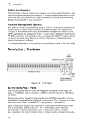
...-232 console port (out-of-band), or you can be configured manually. 1-6 Description of the switch's advanced features, refer to other switches or hubs. (See "1000BASE-T Pin Assignments" on -board Web agent, or Windows-based network management software. This switch also features full-duplex capability on all ports. For a detailed description of Hardware Figure 1-1. Because all network connections to PCs or servers, or to the User Guide. It also includes a management agent...
...-232 console port (out-of-band), or you can be configured manually. 1-6 Description of the switch's advanced features, refer to other switches or hubs. (See "1000BASE-T Pin Assignments" on -board Web agent, or Windows-based network management software. This switch also features full-duplex capability on all ports. For a detailed description of Hardware Figure 1-1. Because all network connections to PCs or servers, or to the User Guide. It also includes a management agent...

Getting Started Guide
Page 23
... 1 SFP transceiver. You must also use of an RJ-45 port or SFP slot, as required. 1 Description of Hardware Each port also supports auto-negotiation of flow control, so the switch can function at a temperature that it can automatically prevent port buffers from becoming saturated. In its default configuration, if an SFP transceiver (purchased separately) is installed in a slot and has a valid link on its port, the...
... 1 SFP transceiver. You must also use of an RJ-45 port or SFP slot, as required. 1 Description of Hardware Each port also supports auto-negotiation of flow control, so the switch can function at a temperature that it can automatically prevent port buffers from becoming saturated. In its default configuration, if an SFP transceiver (purchased separately) is installed in a slot and has a valid link on its port, the...
Getting Started Guide
Page 28
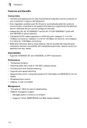
... out-of 16K MAC address entries • Provides store-and-forward switching • Supports wire-speed switching • Supports flow control, using back pressure for half duplex and IEEE 802.3x for full duplex • Broadcast storm control • Desktop or rack-mountable Management • "At-a-glance" LEDs for easy troubleshooting • Network management agent: • Manages switch in legacy LAN equipment. • Auto-negotiation enables each RJ-45 port to automatically select...
... out-of 16K MAC address entries • Provides store-and-forward switching • Supports wire-speed switching • Supports flow control, using back pressure for half duplex and IEEE 802.3x for full duplex • Broadcast storm control • Desktop or rack-mountable Management • "At-a-glance" LEDs for easy troubleshooting • Network management agent: • Manages switch in legacy LAN equipment. • Auto-negotiation enables each RJ-45 port to automatically select...

Getting Started Guide
Page 29
... device and is powered from an independent circuit breaker. Chapter 2: Installing the Switch Selecting a Site Switches can be clearly visible • Make sure twisted-pair cable is always routed away from power lines, fluorescent lighting fixtures and other ) and electromagnetic fields from data based network wiring • Safe connections with no damaged cables, connectors or shields 2-13 Ethernet Cabling To ensure proper operation when installing the switch into a network...
... device and is powered from an independent circuit breaker. Chapter 2: Installing the Switch Selecting a Site Switches can be clearly visible • Make sure twisted-pair cable is always routed away from power lines, fluorescent lighting fixtures and other ) and electromagnetic fields from data based network wiring • Safe connections with no damaged cables, connectors or shields 2-13 Ethernet Cabling To ensure proper operation when installing the switch into a network...

Getting Started Guide
Page 32
2 Installing the Switch 2. Attach the four adhesive feet to a Power Source" at the end of the first switch. Figure 2-3. Attaching the Adhesive Feet 2. If installing multiple switches, mount them in the rack, one below the other, in the rack, using rack-mounting screws (not provided). Figure 2-4. If installing a single switch only, turn to "Connecting to the bottom of this chapter. 4. Mount the device in any order. Installing the Switch in a Rack 3. Desktop or Shelf Mounting 1. Set the device on a flat surface near an AC power source, making sure there 2-16
2 Installing the Switch 2. Attach the four adhesive feet to a Power Source" at the end of the first switch. Figure 2-3. Attaching the Adhesive Feet 2. If installing multiple switches, mount them in the rack, one below the other, in the rack, using rack-mounting screws (not provided). Figure 2-4. If installing a single switch only, turn to "Connecting to the bottom of this chapter. 4. Mount the device in any order. Installing the Switch in a Rack 3. Desktop or Shelf Mounting 1. Set the device on a flat surface near an AC power source, making sure there 2-16

Getting Started Guide
Page 38
... solve a problem. If the device is a PC card and the switch is in place, attach one end of a patch cable to an available port on the switch) corresponding to each connection is made, the green Link LED (on the switch, and the other end of the patch panel. Instructions for the segment attached to a modular wall outlet. 3. Label the cables to simplify future troubleshooting. 3 Making Network Connections 2. Figure...
... solve a problem. If the device is a PC card and the switch is in place, attach one end of a patch cable to an available port on the switch) corresponding to each connection is made, the green Link LED (on the switch, and the other end of the patch panel. Instructions for the segment attached to a modular wall outlet. 3. Label the cables to simplify future troubleshooting. 3 Making Network Connections 2. Figure...

Getting Started Guide
Page 39
... not connected to a fiber cable, the rubber cover should never look directly at Gigabit speed will impair the quality of flow control. The maximum length for connecting to a high-speed server. 3 Fiber Optic SFP Devices Fiber Optic SFP Devices An optional Gigabit SFP transceiver (1000BASE-SX, or 1000BASE-LX) can be replaced to protect the optics. 2. Connect one orientation. As a connection is made, check the green Link LED on the switch corresponding to the port to...
... not connected to a fiber cable, the rubber cover should never look directly at Gigabit speed will impair the quality of flow control. The maximum length for connecting to a high-speed server. 3 Fiber Optic SFP Devices Fiber Optic SFP Devices An optional Gigabit SFP transceiver (1000BASE-SX, or 1000BASE-LX) can be replaced to protect the optics. 2. Connect one orientation. As a connection is made, check the green Link LED on the switch corresponding to the port to...

Getting Started Guide
Page 40
... 5e specification includes test parameters that are only recommendations for 1000BASE-T, providing that all critical connections, or any new cable installations, Category 5e (enhanced Category 5) or Category 6 cable should also work for Category 5. Maximum 1000BASE-T Gigabit Ethernet Cable Length Cable Type Category 5, 5e, 6 100-ohm UTP or STP Maximum Cable Length Connector 100 m (328 ft) RJ-45 Table 3-2. Maximum 1000BASE-LX Gigabit Ethernet Cable Length Fiber Size 9/125...
... 5e specification includes test parameters that are only recommendations for 1000BASE-T, providing that all critical connections, or any new cable installations, Category 5e (enhanced Category 5) or Category 6 cable should also work for Category 5. Maximum 1000BASE-T Gigabit Ethernet Cable Length Cable Type Category 5, 5e, 6 100-ohm UTP or STP Maximum Cable Length Connector 100 m (328 ft) RJ-45 Table 3-2. Maximum 1000BASE-LX Gigabit Ethernet Cable Length Fiber Size 9/125...

Getting Started Guide
Page 43
... isolate the problem, then the internal power supply may have been properly installed. Replace the defective adapter or cable if necessary. • Try power cycling the switch to shutdown. Troubleshooting Chart Troubleshooting Chart Action • Check connections between the switch, the power cord, and the wall outlet. • Contact your dealer for assistance. Appendix A: Troubleshooting Diagnosing Switch Indicators Symptom Power LED is Off Link LED is Off Diag LED is used and its...
... isolate the problem, then the internal power supply may have been properly installed. Replace the defective adapter or cable if necessary. • Try power cycling the switch to shutdown. Troubleshooting Chart Troubleshooting Chart Action • Check connections between the switch, the power cord, and the wall outlet. • Contact your dealer for assistance. Appendix A: Troubleshooting Diagnosing Switch Indicators Symptom Power LED is Off Link LED is Off Diag LED is used and its...
Getting Started Guide
Page 49
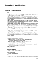
... Power over Ethernet, two Gigabit combo uplink ports (with SFP or 10/100/1000Base-TX interfaces) and two ports full-duplex Gigabit stacking OS-LS-6224U - Category 5, 5e, or 6) Maximum Cable Length - 100 m (328 ft) Buffer Architecture 16 MB Aggregate Bandwidth 12,800 or 17,600 (for 24 port/48 port) Switching Database 16K MAC address entries LEDs System: Power (Power Supply), Diag (Diagnostics), BPS (Backup Power Supply) C-33 Appendix C: Specifications Physical Characteristics Ports OS-LS-6212 - Ethernet based switch...
... Power over Ethernet, two Gigabit combo uplink ports (with SFP or 10/100/1000Base-TX interfaces) and two ports full-duplex Gigabit stacking OS-LS-6224U - Category 5, 5e, or 6) Maximum Cable Length - 100 m (328 ft) Buffer Architecture 16 MB Aggregate Bandwidth 12,800 or 17,600 (for 24 port/48 port) Switching Database 16K MAC address entries LEDs System: Power (Power Supply), Diag (Diagnostics), BPS (Backup Power Supply) C-33 Appendix C: Specifications Physical Characteristics Ports OS-LS-6212 - Ethernet based switch...

Getting Started Guide
Page 53
....3z specification for Gigabit Ethernet over 100-ohm Category 5, 5e or 6 twisted-pair cable (using all four wire pairs). Also synonymous with each other device that does not forward traffic. CSMA/CD CSMA/CD (Carrier Sense Multiple Access/Collision Detect) is connected. Collision Domain Single CSMA/CD LAN segment. Auto-Negotiation Signalling method allowing each node to select its optimum operational mode (e.g., speed and duplex mode...
....3z specification for Gigabit Ethernet over 100-ohm Category 5, 5e or 6 twisted-pair cable (using all four wire pairs). Also synonymous with each other device that does not forward traffic. CSMA/CD CSMA/CD (Carrier Sense Multiple Access/Collision Detect) is connected. Collision Domain Single CSMA/CD LAN segment. Auto-Negotiation Signalling method allowing each node to select its optimum operational mode (e.g., speed and duplex mode...
Getting Started Guide
Page 55
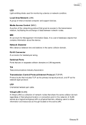
... Management Information Base. A VLAN serves as a logical workgroup with no physical barriers, allowing users to the transmission medium, facilitating the exchange of interconnected computer and support devices. Switched Ports Ports that contains information about the device. Glossary-39 Glossary LED Light emitting diode used for monitoring a device or network condition. Local Area Network (LAN) A group of data between two end stations in the network. Media Access Control (MAC) A portion of the networking protocol...
... Management Information Base. A VLAN serves as a logical workgroup with no physical barriers, allowing users to the transmission medium, facilitating the exchange of interconnected computer and support devices. Switched Ports Ports that contains information about the device. Glossary-39 Glossary LED Light emitting diode used for monitoring a device or network condition. Local Area Network (LAN) A group of data between two end stations in the network. Media Access Control (MAC) A portion of the networking protocol...
Getting Started Guide
Page 57
... desktop mounting 2-16 device connections 3-21 E electrical interference, avoiding 2-13 equipment checklist 2-14 Ethernet connectivity rules 3-25 F Fast Ethernet connectivity rules 3-24, 3-25 features management 1-12 switch 1-12 fiber cables 3-23 G Gigabit Ethernet cable lengths 3-24 grounding for racks 2-15 I IEEE 802.3 Ethernet 1-12 IEEE 802.3u Fast Ethernet 1-12 IEEE 802.3z Gigabit Ethernet 1-12 indicators, LED 1-8 installation connecting devices to the switch 3-21 desktop or shelf mounting 2-16 port connections 3-21 power requirements 2-13 problems 4-27 rack mounting 2-15...
... desktop mounting 2-16 device connections 3-21 E electrical interference, avoiding 2-13 equipment checklist 2-14 Ethernet connectivity rules 3-25 F Fast Ethernet connectivity rules 3-24, 3-25 features management 1-12 switch 1-12 fiber cables 3-23 G Gigabit Ethernet cable lengths 3-24 grounding for racks 2-15 I IEEE 802.3 Ethernet 1-12 IEEE 802.3u Fast Ethernet 1-12 IEEE 802.3z Gigabit Ethernet 1-12 indicators, LED 1-8 installation connecting devices to the switch 3-21 desktop or shelf mounting 2-16 port connections 3-21 power requirements 2-13 problems 4-27 rack mounting 2-15...

