
Operating Instructions
Page 2
... and the provided shielded video interface cables to connect to correct the interference by turning the equipment off and on a circuit different from that to part 15 of the following measures: - Increase the separation between the equipment and receiver. - Please use a power cable is encouraged to try to this device...
... and the provided shielded video interface cables to connect to correct the interference by turning the equipment off and on a circuit different from that to part 15 of the following measures: - Increase the separation between the equipment and receiver. - Please use a power cable is encouraged to try to this device...

Operating Instructions
Page 5
... discharge unit (NEC Section 810-20) Electric service equipment Grounding conductors (NEC Section 810-21) Ground clamp Power service grounding electrode system (NEC Art 250 Part H) Use extreme care to make sure you are never in a position where your body (or any heat source may cause breakage and leakage of the...
... discharge unit (NEC Section 810-20) Electric service equipment Grounding conductors (NEC Section 810-21) Ground clamp Power service grounding electrode system (NEC Art 250 Part H) Use extreme care to make sure you are never in a position where your body (or any heat source may cause breakage and leakage of the...
Operating Instructions
Page 8
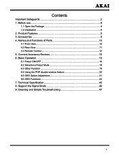
Before use 8 1.1 Open the Package 8 1.2 Installation 8 2. Connect Accessory Devices 15 6. Cleaning and Simple Troubleshooting 47 7 Technical Specification 45 8. Support the Signal Mode 46 9. Contents Important Safeguards 2 1. Product Features 9 3. Names and Functions of Input Mode 18 6.3 Other Function 19 6.4 Using the POP double-window feature 20 6.5 OSD Option Adjustment 21 6.6 OSD Functions 22 7. Accessories 9 4. Basic Operation 18 6.1 Power ON/OFF 18 6.2 Selection of Parts 10 4.1 Front View 10 4.2 Rear View 11 4.3 Remote Control 12 5.
Before use 8 1.1 Open the Package 8 1.2 Installation 8 2. Connect Accessory Devices 15 6. Cleaning and Simple Troubleshooting 47 7 Technical Specification 45 8. Support the Signal Mode 46 9. Contents Important Safeguards 2 1. Product Features 9 3. Names and Functions of Input Mode 18 6.3 Other Function 19 6.4 Using the POP double-window feature 20 6.5 OSD Option Adjustment 21 6.6 OSD Functions 22 7. Accessories 9 4. Basic Operation 18 6.1 Power ON/OFF 18 6.2 Selection of Parts 10 4.1 Front View 10 4.2 Rear View 11 4.3 Remote Control 12 5.

Operating Instructions
Page 11
... as ▲ / ▼ buttons in the OSD Menu screen. Press to turn off . SOURCE: Press to turn on and turn on mode The functions of Parts 4.1 Front View Sketch map Ⱝ POWER Ⱟ IR CH. B. A. SOURCE MENU VOL. They are described as ◄ / ► buttons in the ...OSD Menu screen. Indicator on (Red) Standby mode Indicator on (Green) Power on and off . VOL. NAMES AND FUNCTIONS OF PARTS----FRONT VIEW----REAR VIEW 4. Press again to confirm. 10 When display the OSD-menu, press it to exit the menu. A. B. To scan ...
... as ▲ / ▼ buttons in the OSD Menu screen. Press to turn off . SOURCE: Press to turn on and turn on mode The functions of Parts 4.1 Front View Sketch map Ⱝ POWER Ⱟ IR CH. B. A. SOURCE MENU VOL. They are described as ◄ / ► buttons in the ...OSD Menu screen. Indicator on (Red) Standby mode Indicator on (Green) Power on and off . VOL. NAMES AND FUNCTIONS OF PARTS----FRONT VIEW----REAR VIEW 4. Press again to confirm. 10 When display the OSD-menu, press it to exit the menu. A. B. To scan ...
