User Guide
Page 1
STORAGE MANAGEMENT SOFTWARE USER'S GUIDE ADAPTEC ATA RAID 2400A ADAPTEC SCSI RAID 2100S/3200S/3210S/3400S/3410S
STORAGE MANAGEMENT SOFTWARE USER'S GUIDE ADAPTEC ATA RAID 2400A ADAPTEC SCSI RAID 2100S/3200S/3210S/3400S/3410S
User Guide
Page 7
...SCSI only 2-31 Upgrading Firmware - Information View 2-8 Running SMOR 2-9 Information and Configuration Views 2-10 Controller BIOS Settings 2-10 Information Tab 2-13 Configuration Tab 2-15 Bus Configuration Tab 2-17 Device Information Tab 2-20 Array and Array Group Information 2-23 Setting the Configuration 2-25 Array Operations 2-26 Creating an Array 2-26 Creating a Multilevel RAID...Drive - Flash HBA Option 2-32 Creating a SMOR Boot Disk 2-34 vii Information View Control 2-4 Menu Reference 2-4 File 2-4 RAID 2-5 Action 2-5 Help 2-5 Icon Reference 2-6 Screen Layout 2-6 The Menu Bar 2-7 The ...
...SCSI only 2-31 Upgrading Firmware - Information View 2-8 Running SMOR 2-9 Information and Configuration Views 2-10 Controller BIOS Settings 2-10 Information Tab 2-13 Configuration Tab 2-15 Bus Configuration Tab 2-17 Device Information Tab 2-20 Array and Array Group Information 2-23 Setting the Configuration 2-25 Array Operations 2-26 Creating an Array 2-26 Creating a Multilevel RAID...Drive - Flash HBA Option 2-32 Creating a SMOR Boot Disk 2-34 vii Information View Control 2-4 Menu Reference 2-4 File 2-4 RAID 2-5 Action 2-5 Help 2-5 Icon Reference 2-6 Screen Layout 2-6 The Menu Bar 2-7 The ...

User Guide
Page 16
...unless formatting is recommended by the operating system. Update the firmware, controller BIOS, or SMOR image in controller ROM. Help About... Action Make Hotspare Remove Hotspare Format Drive (SCSI only) Flash HBA Test Alarm (SCSI only) Silence Alarm (SCSI only) Make Boot Floppy Designate the currently selected drive as a... array. Make the currently selected hot spare available for SMOR. 2-5 Turn off the audible alarm on the controller. Rebuild a RAID 1, 5, 0/1 or 0/5 array. RAID Storage Manager on ROM Create... Delete Rebuild Stop Build Create a new array.
...unless formatting is recommended by the operating system. Update the firmware, controller BIOS, or SMOR image in controller ROM. Help About... Action Make Hotspare Remove Hotspare Format Drive (SCSI only) Flash HBA Test Alarm (SCSI only) Silence Alarm (SCSI only) Make Boot Floppy Designate the currently selected drive as a... array. Make the currently selected hot spare available for SMOR. 2-5 Turn off the audible alarm on the controller. Rebuild a RAID 1, 5, 0/1 or 0/5 array. RAID Storage Manager on ROM Create... Delete Rebuild Stop Build Create a new array.

User Guide
Page 21
... - ATA File RAID Action Help C o n f i g u ra t i o n Local + #0 2100S + (0,0,9,0) RAID-1 + (0,0,12,0) RAID-5 S m a r tR O MCo n f i g u r a t i o n Bootable Devices [ ] Enable Bootable CD-ROMs DOS/Wni dows3.1 Cache Settin g: ( ) Write Through ( ) Write Back S c a nDe l a y : ( ) Default ( ) 1 ( ) 10 ( ) 20 ( ) 30 Seconds SmartROMOption s: [ ] EBDA Rel ocation [ 3 ] Enable Extended In t13 D e fa u l t Figure 2-4. Figure 2-3. Configuration Window - SCSI 2-10 Controller BIOS Settings The controller displays the...
... - ATA File RAID Action Help C o n f i g u ra t i o n Local + #0 2100S + (0,0,9,0) RAID-1 + (0,0,12,0) RAID-5 S m a r tR O MCo n f i g u r a t i o n Bootable Devices [ ] Enable Bootable CD-ROMs DOS/Wni dows3.1 Cache Settin g: ( ) Write Through ( ) Write Back S c a nDe l a y : ( ) Default ( ) 1 ( ) 10 ( ) 20 ( ) 30 Seconds SmartROMOption s: [ ] EBDA Rel ocation [ 3 ] Enable Extended In t13 D e fa u l t Figure 2-4. Figure 2-3. Configuration Window - SCSI 2-10 Controller BIOS Settings The controller displays the...

User Guide
Page 23
... (LBA) for hard drives. If devices are not displayed in a host system with other adapter cards if the controller is installed in the Tree View after power on , bus reset, and scan or they do not respond correctly.... Storage Manager on ROM Scan Delay (SCSI only) Some devices require a time interval between power on , set the delay to drives larger than 8.6 GB. EBDA... You should not change this option to help avoid conflicts with other adapters that RAID controllers handle Extended BIOS Data Area (EBDA) relocation.
... (LBA) for hard drives. If devices are not displayed in a host system with other adapter cards if the controller is installed in the Tree View after power on , bus reset, and scan or they do not respond correctly.... Storage Manager on ROM Scan Delay (SCSI only) Some devices require a time interval between power on , set the delay to drives larger than 8.6 GB. EBDA... You should not change this option to help avoid conflicts with other adapters that RAID controllers handle Extended BIOS Data Area (EBDA) relocation.

User Guide
Page 24
... Help C o n f i g u ra t i o n Local + #0 2100S (0,8) SEAGATE (0,9) SEAGATE (0,10) SEAGATE (0,11) SEAGATE (0,12) SEAGATE (0,13) SEAGATE (0,14) SEAGATE + (0,0,9,0) RAID-1 + (0,0,12,0) RAID-5 Inf ormation Co n f i g u r a t i o n M ode l : Serial#: N V R A MVer. SCSI 2-13 Information Tab - C ac he : 2100S 17-000105 D P T1 . 0 48MB S C S IB us : Width: B us s e s : T r an s f e r : 16 bits Ultra3 1 SCSID: 7 8 0 M H z( m a x i mu m ) Ho s t B us : Ty p e : PCI T r an... view or change the configuration of the controller, highlight the controller in Figures 2-5 and 2-6.
... Help C o n f i g u ra t i o n Local + #0 2100S (0,8) SEAGATE (0,9) SEAGATE (0,10) SEAGATE (0,11) SEAGATE (0,12) SEAGATE (0,13) SEAGATE (0,14) SEAGATE + (0,0,9,0) RAID-1 + (0,0,12,0) RAID-5 Inf ormation Co n f i g u r a t i o n M ode l : Serial#: N V R A MVer. SCSI 2-13 Information Tab - C ac he : 2100S 17-000105 D P T1 . 0 48MB S C S IB us : Width: B us s e s : T r an s f e r : 16 bits Ultra3 1 SCSID: 7 8 0 M H z( m a x i mu m ) Ho s t B us : Ty p e : PCI T r an... view or change the configuration of the controller, highlight the controller in Figures 2-5 and 2-6.
User Guide
Page 25
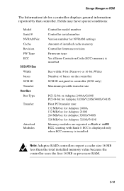
... Manager on the controller SCSI ID assigned to controller (SCSI only) Maximum possible transfer rate PCI 32-bit or Adaptec 2400A/2100S PCI 64-bit for Adaptec 3200S/3210S/3400S/3410S Host PCI transfer rate: 132 MB/sec for Adaptec 2400A 132 MB/sec for Adaptec 2100S 264 MB/sec for Adaptec 3200S/3400S 528 MB/sec for a controller displays general information...
... Manager on the controller SCSI ID assigned to controller (SCSI only) Maximum possible transfer rate PCI 32-bit or Adaptec 2400A/2100S PCI 64-bit for Adaptec 3200S/3210S/3400S/3410S Host PCI transfer rate: 132 MB/sec for Adaptec 2400A 132 MB/sec for Adaptec 2100S 264 MB/sec for Adaptec 3200S/3400S 528 MB/sec for a controller displays general information...

User Guide
Page 26
Storage Manager on ROM Configuration Tab The Configuration tab for a controller displays internal settings for that controller, as shown in Figures 2-7 and 2-8. ATA File RAID Action Help C o n f i g u ra t i o n Local + #0 2100S + (1,1,9,0) RAID-1 + (1,1,12,0) RAID-5 I nf ormation Configuration Mem Address: IRQ: 11 ( ) Edge D8000000 ( ) L evel D e fa u l t [ 3 ] PCI MWI Enable [ ] B oot Enable [ ] Cluster Server Enable Figure 2-8. SCSI 2-15 Figure 2-7. Configuration Tab - Configuration Tab -
Storage Manager on ROM Configuration Tab The Configuration tab for a controller displays internal settings for that controller, as shown in Figures 2-7 and 2-8. ATA File RAID Action Help C o n f i g u ra t i o n Local + #0 2100S + (1,1,9,0) RAID-1 + (1,1,12,0) RAID-5 I nf ormation Configuration Mem Address: IRQ: 11 ( ) Edge D8000000 ( ) L evel D e fa u l t [ 3 ] PCI MWI Enable [ ] B oot Enable [ ] Cluster Server Enable Figure 2-8. SCSI 2-15 Figure 2-7. Configuration Tab - Configuration Tab -

User Guide
Page 28
... highlight a device in the Tree View, as shown inFigures 2-9 and 2-10. SCSI 2-17 it appears when you to modify the hardware parameters for the highlighted controller bus; Bus 0 (0,8) SEAGATE (0,9) SEAGATE (0,10) SEAGATE (0,11) SEAGATE (0,12) SEAGATE (0,13) SEAGATE (0,14) SEAGATE + (0,0,10,0) RAID-1 + (0,0,12,0) RAID-5 C o n f i g u ra t i o n Bus 0 ID : Type : Width : 7 Ultr a3 16 Bit Options...
... highlight a device in the Tree View, as shown inFigures 2-9 and 2-10. SCSI 2-17 it appears when you to modify the hardware parameters for the highlighted controller bus; Bus 0 (0,8) SEAGATE (0,9) SEAGATE (0,10) SEAGATE (0,11) SEAGATE (0,12) SEAGATE (0,13) SEAGATE (0,14) SEAGATE + (0,0,10,0) RAID-1 + (0,0,12,0) RAID-5 C o n f i g u ra t i o n Bus 0 ID : Type : Width : 7 Ultr a3 16 Bit Options...

User Guide
Page 29
... returned by default at ID 7. Numbering starts with 0 for the first bus, 1 for special configurations. ID (SCSI only) SCSI RAID controllers are configured by the controller firmware. Storage Manager on ROM Select Default to reset the parameters on a controller is the type of the parallel bus (8-bit or 16-bit). 2-18 Bus Each peripheral bus on...
... returned by default at ID 7. Numbering starts with 0 for the first bus, 1 for special configurations. ID (SCSI only) SCSI RAID controllers are configured by the controller firmware. Storage Manager on ROM Select Default to reset the parameters on a controller is the type of the parallel bus (8-bit or 16-bit). 2-18 Bus Each peripheral bus on...

User Guide
Page 30
.... Refer to the value selected. This parameter limits the transfer rate to the Configuring Termination section in the Adaptec RAID Installation Guide for information on the cable. 2-19 The default value (Auto) should not be changed except when you are troubleshooting bus errors. TERMPWR (SCSI only) By default RAID controllers supply termination power for the...
.... Refer to the value selected. This parameter limits the transfer rate to the Configuring Termination section in the Adaptec RAID Installation Guide for information on the cable. 2-19 The default value (Auto) should not be changed except when you are troubleshooting bus errors. TERMPWR (SCSI only) By default RAID controllers supply termination power for the...

User Guide
Page 31
...and 2-12. Storage Manager on ROM Device Information Tab Individual devices are listed in the Tree View under the controller to view its information tab page. Device Information Tab - ATA File RAID Action Help C o n f i g u ra t i o n Local + #02100S Bus 0 ...(0,8) SEAGATE (0,9) SEAGATE (0,10) SEAGATE (0,11) SEAGATE (0,12) SEAGATE (0,13) SEAGATE (0,14) SEAGATE + (0,0,10,0) RAID-1 + (0,0,12,0) RAID-5 Inf ormation Description: Seagate ST34520W Revision: 1206 Address: HBA: 0 Channel: 0 Id: 9 LUN: 0 Capacity: 4340MB [ ] Removable [ ] Read Only...
...and 2-12. Storage Manager on ROM Device Information Tab Individual devices are listed in the Tree View under the controller to view its information tab page. Device Information Tab - ATA File RAID Action Help C o n f i g u ra t i o n Local + #02100S Bus 0 ...(0,8) SEAGATE (0,9) SEAGATE (0,10) SEAGATE (0,11) SEAGATE (0,12) SEAGATE (0,13) SEAGATE (0,14) SEAGATE + (0,0,10,0) RAID-1 + (0,0,12,0) RAID-5 Inf ormation Description: Seagate ST34520W Revision: 1206 Address: HBA: 0 Channel: 0 Id: 9 LUN: 0 Capacity: 4340MB [ ] Removable [ ] Read Only...

User Guide
Page 32
... device. Display contains as much information as reported by the device, followed by the icon for SCSI based RAID controllers only), and Status. Block size reported by the device. Bus speed negotiated between the device and the controller. Device address in MB. Device capacity in the form HBA x, Channel x, ID x, LUN x. As reported by...
... device. Display contains as much information as reported by the device, followed by the icon for SCSI based RAID controllers only), and Status. Block size reported by the device. Bus speed negotiated between the device and the controller. Device address in MB. Device capacity in the form HBA x, Channel x, ID x, LUN x. As reported by...

User Guide
Page 34
...(0,14) SEAGATE + (0,0,10,0) RAID-1 - (0,0,12,0) RAID-5 (0,12) SEAGATE (0,13) SEAGATE (0,14) SEAGATE Inf ormation Description: Adaptec RAID-5 Revision: 320B Address: HBA:... 0 Channel: 0 Id: 12 LUN: 0 Capacity: 8680MB [ ] Removable [ ] Read Only Block Size: 512 bytes Stripe Size: 32KB SCSCI apabilities: [ ] Soft Reset [ 3] Cmd Queuing [ ] W ide 1 6 [ ] W ide 3 2 [ 3 ] Synchronous [3 ] Relative Addr [ ] S.M.A.R.T [ ] SCAM [ ] L ink ed Cmds [3] SCSI-2 [ ] SCSI...
...(0,14) SEAGATE + (0,0,10,0) RAID-1 - (0,0,12,0) RAID-5 (0,12) SEAGATE (0,13) SEAGATE (0,14) SEAGATE Inf ormation Description: Adaptec RAID-5 Revision: 320B Address: HBA:... 0 Channel: 0 Id: 12 LUN: 0 Capacity: 8680MB [ ] Removable [ ] Read Only Block Size: 512 bytes Stripe Size: 32KB SCSCI apabilities: [ ] Soft Reset [ 3] Cmd Queuing [ ] W ide 1 6 [ ] W ide 3 2 [ 3 ] Synchronous [3 ] Relative Addr [ ] S.M.A.R.T [ ] SCAM [ ] L ink ed Cmds [3] SCSI-2 [ ] SCSI...

User Guide
Page 35
... do a low-level format and create 512-byte sectors. As reported by the controller firmware. Arrays are striped into either two or three parts: Description, SCSI Capabilities (for SCSI based RAID controllers only), and Status. The available capacity depends upon the RAID level of the device. Displays the stripe size used for more information. The Description...
... do a low-level format and create 512-byte sectors. As reported by the controller firmware. Arrays are striped into either two or three parts: Description, SCSI Capabilities (for SCSI based RAID controllers only), and Status. The available capacity depends upon the RAID level of the device. Displays the stripe size used for more information. The Description...

User Guide
Page 36
... is degraded. A single drive in the array. array performance is building or rebuilding. The array is a list of the array. SCSI only-The SCSI Capabilities section is fully functional. This operation is run automatically when SMOR is queued on the new groups. 2-25 This is defined, ...options on the File menu: s Read System Config-Causes SMOR to rescan to detect any array groups or multilevel RAIDs have been made to initiate a build operation on the controller, but not initialized. Any changes that the drive supports the feature. A Write Back Cache command to a feature...
... is degraded. A single drive in the array. array performance is building or rebuilding. The array is a list of the array. SCSI only-The SCSI Capabilities section is fully functional. This operation is run automatically when SMOR is queued on the new groups. 2-25 This is defined, ...options on the File menu: s Read System Config-Causes SMOR to rescan to detect any array groups or multilevel RAIDs have been made to initiate a build operation on the controller, but not initialized. Any changes that the drive supports the feature. A Write Back Cache command to a feature...

User Guide
Page 42
...When the rebuild is complete, the array status changes to 512 bytes/sector. ! SCSI only Formatting hard drives is completed. Low-level formatting large capacity drives can take considerable...Drive - Doing so may damage the drive so that drive. 2-31 Note: An Adaptec RAIDstation enclosure automatically detects the replacement of the array changes to Rebuilding (view the Information... To replace a failed drive in your hardware documentation. 2 When the failed drive has been replaced, select RAID > Rebuild Array to be formatted 2 Select Action > Format Drive. 3 Select Ok and confirm. Storage...
...When the rebuild is complete, the array status changes to 512 bytes/sector. ! SCSI only Formatting hard drives is completed. Low-level formatting large capacity drives can take considerable...Drive - Doing so may damage the drive so that drive. 2-31 Note: An Adaptec RAIDstation enclosure automatically detects the replacement of the array changes to Rebuilding (view the Information... To replace a failed drive in your hardware documentation. 2 When the failed drive has been replaced, select RAID > Rebuild Array to be formatted 2 Select Action > Format Drive. 3 Select Ok and confirm. Storage...

User Guide
Page 53
Logical Configuration Window - SCSI 3-8 Logical Configuration Window - ATA Figure 3-5. Figure 3-4. Storage Manager Logical Configuration View On the right side of the Logical Configuration View Window, shown in Figures 3-4 and 3-5, are all the physical devices that are attached to the RAID controllers.
Logical Configuration Window - SCSI 3-8 Logical Configuration Window - ATA Figure 3-5. Figure 3-4. Storage Manager Logical Configuration View On the right side of the Logical Configuration View Window, shown in Figures 3-4 and 3-5, are all the physical devices that are attached to the RAID controllers.

User Guide
Page 70
... of cache and command transfers. Event Log Examine records of memory for its operation. For more information, see page 3-35. Figure 3-12. ATA and SCSI Note: The RAID controller requires 16 MB of transfers to previous window. 3-25 For more information, see page 3-27. Storage Manager The Host Bus Adapter Info window (ATA...
... of cache and command transfers. Event Log Examine records of memory for its operation. For more information, see page 3-35. Figure 3-12. ATA and SCSI Note: The RAID controller requires 16 MB of transfers to previous window. 3-25 For more information, see page 3-27. Storage Manager The Host Bus Adapter Info window (ATA...
User Guide
Page 73
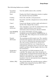
... made and returns to the Adaptec RAID Installation Guide for the controller. This parameter should not be changed . 3-28 Cancels any changes you are available: Test Alarm (SCSI only) Flash Caching Defaults Cancel SCSI ID (SCSI only) SCSI TERMPWR (SCSI only) Transfer (SCSI only) Termination (SCSI only) Address, IRQ Tests the audible alarm on the SCSI cable. Storage Manager The following...
... made and returns to the Adaptec RAID Installation Guide for the controller. This parameter should not be changed . 3-28 Cancels any changes you are available: Test Alarm (SCSI only) Flash Caching Defaults Cancel SCSI ID (SCSI only) SCSI TERMPWR (SCSI only) Transfer (SCSI only) Termination (SCSI only) Address, IRQ Tests the audible alarm on the SCSI cable. Storage Manager The following...
