User Guide
Page 1
STORAGE MANAGEMENT SOFTWARE USER'S GUIDE ADAPTEC ATA RAID 2400A ADAPTEC SCSI RAID 2100S/3200S/3210S/3400S/3410S
STORAGE MANAGEMENT SOFTWARE USER'S GUIDE ADAPTEC ATA RAID 2400A ADAPTEC SCSI RAID 2100S/3200S/3210S/3400S/3410S
User Guide
Page 7
... Array Operations 2-26 Creating an Array 2-26 Creating a Multilevel RAID 2-28 Deleting an Array 2-29 Hot Spares 2-30 Rebuilding a Failed Array 2-31 Formatting a Drive - Contents 1 Storage Management Software Overview 2 Storage Manager on ROM Overview 2-2 Keyboard Reference 2-3 Menu Control 2-3 Left Pane - Tree View Control 2-4 Right Pane - SCSI only 2-31 Upgrading Firmware - Flash HBA Option 2-32...
... Array Operations 2-26 Creating an Array 2-26 Creating a Multilevel RAID 2-28 Deleting an Array 2-29 Hot Spares 2-30 Rebuilding a Failed Array 2-31 Formatting a Drive - Contents 1 Storage Management Software Overview 2 Storage Manager on ROM Overview 2-2 Keyboard Reference 2-3 Menu Control 2-3 Left Pane - Tree View Control 2-4 Right Pane - SCSI only 2-31 Upgrading Firmware - Flash HBA Option 2-32...

User Guide
Page 8
... Failures 3-45 Audible Alarm (SCSI Only) 3-45 Rebuilding a Degraded Array 3-46 Assigning Hot Spares 3-47 Running a Verify Process 3-48 Background Task Priority 3-48 Controller I/O Statistics 3-49 Cache Statistics 3-51 Command Statistics 3-51 Device I/O Statistics 3-51 Remote Communication 3-54 Connecting Across a Network 3-55 Installation and Configuration 3-55 viii Adaptec 3200S/ 3210S/3400S/3410S Only 3-26...
... Failures 3-45 Audible Alarm (SCSI Only) 3-45 Rebuilding a Degraded Array 3-46 Assigning Hot Spares 3-47 Running a Verify Process 3-48 Background Task Priority 3-48 Controller I/O Statistics 3-49 Cache Statistics 3-51 Command Statistics 3-51 Device I/O Statistics 3-51 Remote Communication 3-54 Connecting Across a Network 3-55 Installation and Configuration 3-55 viii Adaptec 3200S/ 3210S/3400S/3410S Only 3-26...

User Guide
Page 12
SCSI only ➤ Upgrading Firmware - Flash HBA Option ➤ Creating a SMOR Boot Disk 2-2 2-3 2-4 2-6 2-6 2-9 2-10 2-25 2-26 2-31 2-32 2-34 2-1 2 Storage Manager on ROM In this Chapter ➤ Overview ➤ Keyboard Reference ➤ Menu Reference ➤ Icon Reference ➤ Screen Layout ➤ Running SMOR ➤ Information and Configuration Views ➤ Setting the Configuration ➤ Array Operations ➤ Formatting a Drive -
SCSI only ➤ Upgrading Firmware - Flash HBA Option ➤ Creating a SMOR Boot Disk 2-2 2-3 2-4 2-6 2-6 2-9 2-10 2-25 2-26 2-31 2-32 2-34 2-1 2 Storage Manager on ROM In this Chapter ➤ Overview ➤ Keyboard Reference ➤ Menu Reference ➤ Icon Reference ➤ Screen Layout ➤ Running SMOR ➤ Information and Configuration Views ➤ Setting the Configuration ➤ Array Operations ➤ Formatting a Drive -

User Guide
Page 16
... the audible alarm on the controller. Turn off the audible alarm on the controller. Rebuild a RAID 1, 5, 0/1 or 0/5 array. Update the firmware, controller BIOS, or SMOR image in controller ROM. Stop building or rebuilding an array. Action Make Hotspare Remove Hotspare Format Drive (SCSI only) Flash HBA Test Alarm (SCSI only) Silence Alarm (SCSI only) Make Boot Floppy Designate...
... the audible alarm on the controller. Turn off the audible alarm on the controller. Rebuild a RAID 1, 5, 0/1 or 0/5 array. Update the firmware, controller BIOS, or SMOR image in controller ROM. Stop building or rebuilding an array. Action Make Hotspare Remove Hotspare Format Drive (SCSI only) Flash HBA Test Alarm (SCSI only) Silence Alarm (SCSI only) Make Boot Floppy Designate...

User Guide
Page 21
Figure 2-3. Controller BIOS Settings The controller displays the default Information View when SMOR starts, as shown in Figures 2-3 and 2-4. ATA File RAID Action Help C o n f i g u ra t i o n Local + #0 2100S + (0,0,9,0) RAID-1 + (0,0,12,0) RAID-5 S m a r tR O MCo n f i g u r a t i o n Bootable Devices [ ] Enable Bootable CD-ROMs DOS/Wni dows3.1 Cache Settin g: ( ) Write Through ( ) Write Back S c a nDe l a y : ( ) Default ( ) 1 ( ) 10 (... an item within the Tree View, the corresponding Information View is displayed. Configuration Window - SCSI 2-10 Configuration Window -
Figure 2-3. Controller BIOS Settings The controller displays the default Information View when SMOR starts, as shown in Figures 2-3 and 2-4. ATA File RAID Action Help C o n f i g u ra t i o n Local + #0 2100S + (0,0,9,0) RAID-1 + (0,0,12,0) RAID-5 S m a r tR O MCo n f i g u r a t i o n Bootable Devices [ ] Enable Bootable CD-ROMs DOS/Wni dows3.1 Cache Settin g: ( ) Write Through ( ) Write Back S c a nDe l a y : ( ) Default ( ) 1 ( ) 10 (... an item within the Tree View, the corresponding Information View is displayed. Configuration Window - SCSI 2-10 Configuration Window -

User Guide
Page 23
LBA enables operating system access to help avoid conflicts with other adapters that RAID controllers handle Extended BIOS Data Area (EBDA) relocation. EBDA Relocation This setting determines the way that follow standard EBDA relocation rules. Enable Extended Int13 This option ... hard drives. You should not change this option to drives larger than 8.6 GB. You can enable this setting. 2-12 Storage Manager on ROM Scan Delay (SCSI only) Some devices require a time interval between power on , set the delay to a longer interval. If devices are not displayed in a host system with ...
LBA enables operating system access to help avoid conflicts with other adapters that RAID controllers handle Extended BIOS Data Area (EBDA) relocation. EBDA Relocation This setting determines the way that follow standard EBDA relocation rules. Enable Extended Int13 This option ... hard drives. You should not change this option to drives larger than 8.6 GB. You can enable this setting. 2-12 Storage Manager on ROM Scan Delay (SCSI only) Some devices require a time interval between power on , set the delay to a longer interval. If devices are not displayed in a host system with ...

User Guide
Page 24
...i o n Local + #0 2100S (0,8) SEAGATE (0,9) SEAGATE (0,10) SEAGATE (0,11) SEAGATE (0,12) SEAGATE (0,13) SEAGATE (0,14) SEAGATE + (0,0,9,0) RAID-1 + (0,0,12,0) RAID-5 Inf ormation Co n f i g u r a t i o n M ode l : Serial#: N V R A MVer. Information Tab - Available tabs are Information and Configuration, as shown in the Tree View. SCSI 2-13 C ac he : 2100S 17-000105 D P T1 . 0 48MB S C S IB us : Width: B us s e s :...Storage Manager on ROM Information Tab To view or change the configuration of the controller, highlight the controller in Figures 2-5 and 2-6. Figure 2-5.
...i o n Local + #0 2100S (0,8) SEAGATE (0,9) SEAGATE (0,10) SEAGATE (0,11) SEAGATE (0,12) SEAGATE (0,13) SEAGATE (0,14) SEAGATE + (0,0,9,0) RAID-1 + (0,0,12,0) RAID-5 Inf ormation Co n f i g u r a t i o n M ode l : Serial#: N V R A MVer. Information Tab - Available tabs are Information and Configuration, as shown in the Tree View. SCSI 2-13 C ac he : 2100S 17-000105 D P T1 . 0 48MB S C S IB us : Width: B us s e s :...Storage Manager on ROM Information Tab To view or change the configuration of the controller, highlight the controller in Figures 2-5 and 2-6. Figure 2-5.
User Guide
Page 25
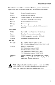
... Manager on the controller SCSI ID assigned to controller (SCSI only) Maximum possible transfer rate PCI 32-bit or Adaptec 2400A/2100S PCI 64-bit for Adaptec 3200S/3210S/3400S/3410S Host PCI transfer rate: 132 MB/sec for Adaptec 2400A 132 MB/sec for Adaptec 2100S 264 MB/sec for Adaptec 3200S/3400S 528 MB/sec for a controller displays general information...
... Manager on the controller SCSI ID assigned to controller (SCSI only) Maximum possible transfer rate PCI 32-bit or Adaptec 2400A/2100S PCI 64-bit for Adaptec 3200S/3210S/3400S/3410S Host PCI transfer rate: 132 MB/sec for Adaptec 2400A 132 MB/sec for Adaptec 2100S 264 MB/sec for Adaptec 3200S/3400S 528 MB/sec for a controller displays general information...

User Guide
Page 26
Configuration Tab - SCSI 2-15 Storage Manager on ROM Configuration Tab The Configuration tab for a controller displays internal settings for that controller, as shown in Figures 2-7 and 2-8. Figure 2-7. Configuration Tab - ATA File RAID Action Help C o n f i g u ra t i o n Local + #0 2100S + (1,1,9,0) RAID-1 + (1,1,12,0) RAID-5 I nf ormation Configuration Mem Address: IRQ: 11 ( ) Edge D8000000 ( ) L evel D e fa u l t [ 3 ] PCI MWI Enable [ ] B oot Enable [ ] Cluster Server Enable Figure 2-8.
Configuration Tab - SCSI 2-15 Storage Manager on ROM Configuration Tab The Configuration tab for a controller displays internal settings for that controller, as shown in Figures 2-7 and 2-8. Figure 2-7. Configuration Tab - ATA File RAID Action Help C o n f i g u ra t i o n Local + #0 2100S + (1,1,9,0) RAID-1 + (1,1,12,0) RAID-5 I nf ormation Configuration Mem Address: IRQ: 11 ( ) Edge D8000000 ( ) L evel D e fa u l t [ 3 ] PCI MWI Enable [ ] B oot Enable [ ] Cluster Server Enable Figure 2-8.

User Guide
Page 28
... 2-9 and 2-10. Bus 0 (0,8) SEAGATE (0,9) SEAGATE (0,10) SEAGATE (0,11) SEAGATE (0,12) SEAGATE (0,13) SEAGATE (0,14) SEAGATE + (0,0,10,0) RAID-1 + (0,0,12,0) RAID-5 C o n f i g u ra t i o n Bus 0 ID : Type : Width : 7 Ultr a3 16 Bit Options [3] TERMPWR Transfer Raet : Termination : Ultra3 Auto D e fa u l t Figure 2-10. it appears when you to modify the hardware parameters for the highlighted controller bus; Figure 2-9.
... 2-9 and 2-10. Bus 0 (0,8) SEAGATE (0,9) SEAGATE (0,10) SEAGATE (0,11) SEAGATE (0,12) SEAGATE (0,13) SEAGATE (0,14) SEAGATE + (0,0,10,0) RAID-1 + (0,0,12,0) RAID-5 C o n f i g u ra t i o n Bus 0 ID : Type : Width : 7 Ultr a3 16 Bit Options [3] TERMPWR Transfer Raet : Termination : Ultra3 Auto D e fa u l t Figure 2-10. it appears when you to modify the hardware parameters for the highlighted controller bus; Figure 2-9.

User Guide
Page 29
... the type of the parallel bus (8-bit or 16-bit). 2-18 This value should not be changed unless required for the controller Auto On Available Settings SCSI: 0 - 6 ATA: not shown N/A N/A Ultra3, Ultra2, Ultra, 10, 8, 5 Asynchronous On, Off, High Only Auto, Off Note: ... Termination TERMPWR Default 7 As reported As reported Maximum allowed for special configurations. Bus Each peripheral bus on . ID (SCSI only) SCSI RAID controllers are configured by the controller firmware. Width (SCSI only) The width of bus (Ultra, Ultra2, Ultra3, ATA/100, etc.). Type This is assigned a number....
... the type of the parallel bus (8-bit or 16-bit). 2-18 This value should not be changed unless required for the controller Auto On Available Settings SCSI: 0 - 6 ATA: not shown N/A N/A Ultra3, Ultra2, Ultra, 10, 8, 5 Asynchronous On, Off, High Only Auto, Off Note: ... Termination TERMPWR Default 7 As reported As reported Maximum allowed for special configurations. Bus Each peripheral bus on . ID (SCSI only) SCSI RAID controllers are configured by the controller firmware. Width (SCSI only) The width of bus (Ultra, Ultra2, Ultra3, ATA/100, etc.). Type This is assigned a number....

User Guide
Page 30
TERMPWR (SCSI only) By default RAID controllers supply termination power for other devices through the TERMPWR line on setting this is usually an indication that the bus is too long or that the bus is not terminated correctly. Storage Manager on ROM Transfer Rate (SCSI only) The controller automatically negotiates with each... except when you are troubleshooting bus errors. Note: On buses, if setting this parameter to the Configuring Termination section in the Adaptec RAID Installation Guide for the controller and bus. Refer to 5 MHz eliminates bus data errors, this parameter.
TERMPWR (SCSI only) By default RAID controllers supply termination power for other devices through the TERMPWR line on setting this is usually an indication that the bus is too long or that the bus is not terminated correctly. Storage Manager on ROM Transfer Rate (SCSI only) The controller automatically negotiates with each... except when you are troubleshooting bus errors. Note: On buses, if setting this parameter to the Configuring Termination section in the Adaptec RAID Installation Guide for the controller and bus. Refer to 5 MHz eliminates bus data errors, this parameter.

User Guide
Page 31
...+ #02100S Bus 0 (0,8) SEAGATE (0,9) SEAGATE (0,10) SEAGATE (0,11) SEAGATE (0,12) SEAGATE (0,13) SEAGATE (0,14) SEAGATE + (0,0,10,0) RAID-1 + (0,0,12,0) RAID-5 Inf ormation Description: Seagate ST34520W Revision: 1206 Address: HBA: 0 Channel: 0 Id: 9 LUN: 0 Capacity: 4340MB [ ] Removable ...SCAM [ ] L ink ed Cmds [3] SCSI-2 [ ] SCSI-3 Status: Optimal Figure 2-12. Storage Manager on ROM Device Information Tab Individual devices are listed in the Tree View under the controller to view its information tab page. Device Information Tab - SCSI 2-20 Highlight a device to which they...
...+ #02100S Bus 0 (0,8) SEAGATE (0,9) SEAGATE (0,10) SEAGATE (0,11) SEAGATE (0,12) SEAGATE (0,13) SEAGATE (0,14) SEAGATE + (0,0,10,0) RAID-1 + (0,0,12,0) RAID-5 Inf ormation Description: Seagate ST34520W Revision: 1206 Address: HBA: 0 Channel: 0 Id: 9 LUN: 0 Capacity: 4340MB [ ] Removable ...SCAM [ ] L ink ed Cmds [3] SCSI-2 [ ] SCSI-3 Status: Optimal Figure 2-12. Storage Manager on ROM Device Information Tab Individual devices are listed in the Tree View under the controller to view its information tab page. Device Information Tab - SCSI 2-20 Highlight a device to which they...

User Guide
Page 32
... capacity is for negotiated bus speed and transfer path (8-bit, 16-bit). 2-21 Bus speed negotiated between the device and the controller. Device firmware revision. Maximum transfer rate for the currently inserted media or no media inserted if no media is divided into either two ...general information and configuration. Device address in MB. Display contains as much information as reported by the device, followed by the icon for SCSI based RAID controllers only), and Status. Tape drives do not report media. As reported by device. This view is inserted. Device capacity in the ...
... capacity is for negotiated bus speed and transfer path (8-bit, 16-bit). 2-21 Bus speed negotiated between the device and the controller. Device firmware revision. Maximum transfer rate for the currently inserted media or no media inserted if no media is divided into either two ...general information and configuration. Device address in MB. Display contains as much information as reported by the device, followed by the icon for SCSI based RAID controllers only), and Status. Tape drives do not report media. As reported by device. This view is inserted. Device capacity in the ...

User Guide
Page 33
... Storage Manager on ROM The status condition is operational, but has been initialized as part of an array. Drive is one of controller capabilities. failure prediction. If the device becomes available, it only changes status after the system configuration is read or the host is ... devices: Dead Failed Impacted Missing Optimal Uninitialized Verify Warning Device failed to respond to commands on a device with a S.M.A.R.T. SCSI only-The SCSI Capabilities section is restarted. Performance degradation in response to a feature indicates that the drive supports the feature. 2-22
... Storage Manager on ROM The status condition is operational, but has been initialized as part of an array. Drive is one of controller capabilities. failure prediction. If the device becomes available, it only changes status after the system configuration is read or the host is ... devices: Dead Failed Impacted Missing Optimal Uninitialized Verify Warning Device failed to respond to commands on a device with a S.M.A.R.T. SCSI only-The SCSI Capabilities section is restarted. Performance degradation in response to a feature indicates that the drive supports the feature. 2-22

User Guide
Page 34
...(0,11) SEAGATE (0,12) SEAGATE (0,13) SEAGATE (0,14) SEAGATE + (0,0,10,0) RAID-1 - (0,0,12,0) RAID-5 (0,12) SEAGATE (0,13) SEAGATE (0,14) SEAGATE Inf ormation Description: Adaptec RAID-5 Revision: 320B Address: HBA: 0 Channel: 0 Id: 12 LUN: 0 ...Capacity: 8680MB [ ] Removable [ ] Read Only Block Size: 512 bytes Stripe Size: 32KB SCSCI apabilities: [ ] Soft Reset [ 3] Cmd Queuing [ ] W ide 1 6 [ ] W ide 3 2 [ 3 ] Synchronous [3 ] Relative Addr [ ] S.M.A.R.T [ ] SCAM [ ] L ink ed Cmds [3] SCSI-2 [ ] SCSI...
...(0,11) SEAGATE (0,12) SEAGATE (0,13) SEAGATE (0,14) SEAGATE + (0,0,10,0) RAID-1 - (0,0,12,0) RAID-5 (0,12) SEAGATE (0,13) SEAGATE (0,14) SEAGATE Inf ormation Description: Adaptec RAID-5 Revision: 320B Address: HBA: 0 Channel: 0 Id: 12 LUN: 0 ...Capacity: 8680MB [ ] Removable [ ] Read Only Block Size: 512 bytes Stripe Size: 32KB SCSCI apabilities: [ ] Soft Reset [ 3] Cmd Queuing [ ] W ide 1 6 [ ] W ide 3 2 [ 3 ] Synchronous [3 ] Relative Addr [ ] S.M.A.R.T [ ] SCAM [ ] L ink ed Cmds [3] SCSI-2 [ ] SCSI...

User Guide
Page 35
...Config action has been performed. After you create the arrays, one or more information. Controllers always are comprised of multiple pairs of drives greater than 1. Displays the stripe size used for SCSI based RAID controllers only), and Status. Note: Arrays do a low-level format and create 512-...byte sectors. RAID 5 arrays contain three or more drives. RAID address in bytes. The sector (block) size of that array....
...Config action has been performed. After you create the arrays, one or more information. Controllers always are comprised of multiple pairs of drives greater than 1. Displays the stripe size used for SCSI based RAID controllers only), and Status. Note: Arrays do a low-level format and create 512-...byte sectors. RAID 5 arrays contain three or more drives. RAID address in bytes. The sector (block) size of that array....

User Guide
Page 36
.... A check mark next to a feature indicates that have been created or modified, this operation causes the controller to detect any array groups or multilevel RAIDs have been made and not saved are listed below: Building Created Dead Degraded Impacted Optimal Pending Rebuilding The array... the array is building or rebuilding. I/O performance is a list of controller capabilities. If any changes in the array failed; The array or device is being performed on the array; SCSI only-The SCSI Capabilities section is affected. A single drive in hardware configuration or status....
.... A check mark next to a feature indicates that have been created or modified, this operation causes the controller to detect any array groups or multilevel RAIDs have been made and not saved are listed below: Building Created Dead Degraded Impacted Optimal Pending Rebuilding The array... the array is building or rebuilding. I/O performance is a list of controller capabilities. If any changes in the array failed; The array or device is being performed on the array; SCSI only-The SCSI Capabilities section is affected. A single drive in hardware configuration or status....

User Guide
Page 42
...a sector size other than 512 bytes, low-level format the drive to 512 bytes/sector. ! Note: An Adaptec RAIDstation enclosure automatically detects the replacement of the array changes to Optimal. SCSI only Formatting hard drives is online. However, if you have a drive that it requires factory repair or replacement...: 1 Remove and replace the failed drive according the procedures in your hardware documentation. 2 When the failed drive has been replaced, select RAID > Rebuild Array to start the rebuild process. Low-level formatting large capacity drives can take considerable time.
...a sector size other than 512 bytes, low-level format the drive to 512 bytes/sector. ! Note: An Adaptec RAIDstation enclosure automatically detects the replacement of the array changes to Optimal. SCSI only Formatting hard drives is online. However, if you have a drive that it requires factory repair or replacement...: 1 Remove and replace the failed drive according the procedures in your hardware documentation. 2 When the failed drive has been replaced, select RAID > Rebuild Array to start the rebuild process. Low-level formatting large capacity drives can take considerable time.
