Installation Guide
Page 8
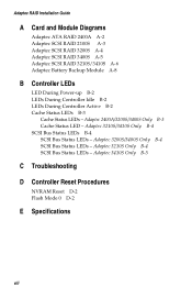
...Status LEDs - Adaptec 3410S Only B-5 C Troubleshooting D Controller Reset Procedures NVRAM Reset D-2 Flash Mode 0 D-2 E Specifications viii Adaptec 2400A/3200S/3400S Only B-3 Cache Status LED - Adaptec 3210S/3410S Only B-4 SCSI Bus Status LEDs B-4 SCSI Bus Status LEDs - Adaptec RAID Installation Guide A Card and Module Diagrams Adaptec ATA RAID 2400A A-2 Adaptec SCSI RAID 2100S A-3 Adaptec SCSI RAID 3200S A-4 Adaptec SCSI RAID 3400S A-5 Adaptec SCSI RAID 3210S/3410S A-6 Adaptec Battery Backup Module A-8 B Controller LEDs LED During Power-up B-2 LEDs During Controller Idle B-2 LEDs During...
...Status LEDs - Adaptec 3410S Only B-5 C Troubleshooting D Controller Reset Procedures NVRAM Reset D-2 Flash Mode 0 D-2 E Specifications viii Adaptec 2400A/3200S/3400S Only B-3 Cache Status LED - Adaptec 3210S/3410S Only B-4 SCSI Bus Status LEDs B-4 SCSI Bus Status LEDs - Adaptec RAID Installation Guide A Card and Module Diagrams Adaptec ATA RAID 2400A A-2 Adaptec SCSI RAID 2100S A-3 Adaptec SCSI RAID 3200S A-4 Adaptec SCSI RAID 3400S A-5 Adaptec SCSI RAID 3210S/3410S A-6 Adaptec Battery Backup Module A-8 B Controller LEDs LED During Power-up B-2 LEDs During Controller Idle B-2 LEDs During...

Installation Guide
Page 20
... MB of cache installed. Requirements for the location of the LED. Therefore, the RAID software shows 16 MB less than is not recommended.) Refer to Appendix A for non-Adaptec memory are in the following table: Controller Sockets Available Capacities (MB) Type Adaptec 2400A Adaptec 2100S Adaptec 3210S Adaptec 3410S Adaptec 3200S/ 3400S 1 32 (as shipped), 3.3-V, 100-MHz (or faster) 1 64...
... MB of cache installed. Requirements for the location of the LED. Therefore, the RAID software shows 16 MB less than is not recommended.) Refer to Appendix A for non-Adaptec memory are in the following table: Controller Sockets Available Capacities (MB) Type Adaptec 2400A Adaptec 2100S Adaptec 3210S Adaptec 3410S Adaptec 3200S/ 3400S 1 32 (as shipped), 3.3-V, 100-MHz (or faster) 1 64...
Installation Guide
Page 32
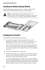
... slot) will become the booting controller, you require the RAID controller to become the booting controller. See Appendix A for the location of the LED cable (usually a red wire or a wire marked with a red stripe) is attached to pin 1 or 3 and the negative lead (usually a black wire) is for your controller model. Adaptec RAID Installation Guide Installing the Battery...
... slot) will become the booting controller, you require the RAID controller to become the booting controller. See Appendix A for the location of the LED cable (usually a red wire or a wire marked with a red stripe) is attached to pin 1 or 3 and the negative lead (usually a black wire) is for your controller model. Adaptec RAID Installation Guide Installing the Battery...

Installation Guide
Page 80
Adaptec RAID Installation Guide Adaptec ATA RAID 2400A IRQ ECCEN ECCERR 8 7 6 5 4 3 2 1 J1 J7 LEDs J8 J10 1 Busy LED J4 IDE 0 J11 IDE 1 J6 IDE 2 J12 IDE 3 J16 SIMM Socket P1 PCI Connector Part ECCEN ECCERR IRQ, 8..1 J1 J4 J6 J7 J8 J10 J11 J12 J16 P1 Description ECC enabled LED (green) ECC error LED (red) Adapter activity LEDs... NVRAM reset IDE 0 cable connector IDE 2 cable connector Reserved-do not use Flash Mode 0 Hard drive activity LED connector IDE 1 cable connector IDE 3 cable ...
Adaptec RAID Installation Guide Adaptec ATA RAID 2400A IRQ ECCEN ECCERR 8 7 6 5 4 3 2 1 J1 J7 LEDs J8 J10 1 Busy LED J4 IDE 0 J11 IDE 1 J6 IDE 2 J12 IDE 3 J16 SIMM Socket P1 PCI Connector Part ECCEN ECCERR IRQ, 8..1 J1 J4 J6 J7 J8 J10 J11 J12 J16 P1 Description ECC enabled LED (green) ECC error LED (red) Adapter activity LEDs... NVRAM reset IDE 0 cable connector IDE 2 cable connector Reserved-do not use Flash Mode 0 Hard drive activity LED connector IDE 1 cable connector IDE 3 cable ...
Installation Guide
Page 81
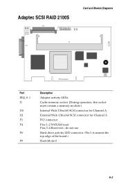
Adaptec SCSI RAID 2100S J10 P6 P4 IRQ8 7 6 5 4 3 2 1 J1 J11 Card and Module Diagrams P9 PCI Connector Part IRQ, 8..1 J1 J10 J11 P1 P4 P6 P9 Description Adapter activity LEDs Cache memory socket. (During operation, this socket must contain a memory module.) Internal Wide Ultra160 SCSI connector for Channel A External Wide Ultra160 SCSI connector for Channel A PCI connector Pins 1-2 NVRAM reset Pins 3-4 Reserved-do not use Hard drive activity LED connector. (Pin 1 is nearest the top edge of the board.) Flash Mode 0 A-3
Adaptec SCSI RAID 2100S J10 P6 P4 IRQ8 7 6 5 4 3 2 1 J1 J11 Card and Module Diagrams P9 PCI Connector Part IRQ, 8..1 J1 J10 J11 P1 P4 P6 P9 Description Adapter activity LEDs Cache memory socket. (During operation, this socket must contain a memory module.) Internal Wide Ultra160 SCSI connector for Channel A External Wide Ultra160 SCSI connector for Channel A PCI connector Pins 1-2 NVRAM reset Pins 3-4 Reserved-do not use Hard drive activity LED connector. (Pin 1 is nearest the top edge of the board.) Flash Mode 0 A-3
Installation Guide
Page 82
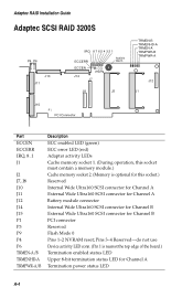
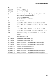
Adaptec RAID Installation Guide Adaptec SCSI RAID 3200S P4 P6 J10 J11 IRQ 8 7 6 5 4 3 2 1 ECCERR ECCEN P3 P9 J14 J7 Audible Alarm J8 J2 TRMEN-B TRMENHD-A TRMEN-A TRMPWR-B TRMPWR-A J12 J1 J15 P1 ... ECCERR IRQ, 8..1 J1 J2 J7, J8 J10 J11 J12 J14 J15 P1 P3 P9 P4 P6 TRMEN-A/B TRMENHD-A TRMPWR-A/B Description ECC enabled LED (green) ECC error LED (red) Adapter activity LEDs Cache memory socket 1. (During operation, this socket must contain a memory module.) Cache memory socket 2. (Memory is nearest the top edge of the...
Adaptec RAID Installation Guide Adaptec SCSI RAID 3200S P4 P6 J10 J11 IRQ 8 7 6 5 4 3 2 1 ECCERR ECCEN P3 P9 J14 J7 Audible Alarm J8 J2 TRMEN-B TRMENHD-A TRMEN-A TRMPWR-B TRMPWR-A J12 J1 J15 P1 ... ECCERR IRQ, 8..1 J1 J2 J7, J8 J10 J11 J12 J14 J15 P1 P3 P9 P4 P6 TRMEN-A/B TRMENHD-A TRMPWR-A/B Description ECC enabled LED (green) ECC error LED (red) Adapter activity LEDs Cache memory socket 1. (During operation, this socket must contain a memory module.) Cache memory socket 2. (Memory is nearest the top edge of the...

Installation Guide
Page 83
...Adaptec SCSI RAID 3400S P4 P6 J10 J11 IRQ 8 7 6 5 4 3 2 1 ECCERR Audible Alarm ECCEN J14 J7 P3 P9 J8 J2 TRMEN-B TRMENHD-A TRMEN-A TRMP WR -B TRMP WR -A J12 J1 J15 PCI Connector Part ECCEN ECCERR IRQ, 8..1 J1 J2 J12 P3 P1 P4 P6 P9 TRMEN-A/B TRMENHD-A TRMPWR-A/B Description ECC enabled LED (green) ECC error LED... (red) Adapter activity LEDs Cache memory socket 1. (During operation, this socket must contain a memory module.) Cache memory socket 2. (Memory is...
...Adaptec SCSI RAID 3400S P4 P6 J10 J11 IRQ 8 7 6 5 4 3 2 1 ECCERR Audible Alarm ECCEN J14 J7 P3 P9 J8 J2 TRMEN-B TRMENHD-A TRMEN-A TRMP WR -B TRMP WR -A J12 J1 J15 PCI Connector Part ECCEN ECCERR IRQ, 8..1 J1 J2 J12 P3 P1 P4 P6 P9 TRMEN-A/B TRMENHD-A TRMPWR-A/B Description ECC enabled LED (green) ECC error LED... (red) Adapter activity LEDs Cache memory socket 1. (During operation, this socket must contain a memory module.) Cache memory socket 2. (Memory is...

Installation Guide
Page 84
Adaptec RAID Installation Guide Adaptec SCSI RAID 3210S/3410S J10 J11 J14 J5 J18 NVRAM M ISC L Busy LED Not available on Model 3210S AAddapteecc J16 AIC--7899W PCI Connector Audible Alarm J19 Front View HPT370 J12 J6 J1 ECCERR TERMEN_A IRQ TPOWERA 1 2 3 TERMEN_B TPOWERB 4 TERMEN_C 5 6 7 TPOWERC TERMEN_D 8 TPOWERD Back View - LEDs Only A-6
Adaptec RAID Installation Guide Adaptec SCSI RAID 3210S/3410S J10 J11 J14 J5 J18 NVRAM M ISC L Busy LED Not available on Model 3210S AAddapteecc J16 AIC--7899W PCI Connector Audible Alarm J19 Front View HPT370 J12 J6 J1 ECCERR TERMEN_A IRQ TPOWERA 1 2 3 TERMEN_B TPOWERB 4 TERMEN_C 5 6 7 TPOWERC TERMEN_D 8 TPOWERD Back View - LEDs Only A-6
Installation Guide
Page 85
... J10 J11 J12 J14 J16 J18 J19 TPOWERA TPOWERB TPOWERC TPOWERD TERMEN_A TERMEN_B TERMEN_C TERMEN_D Description ECC Error LED (red) Adapter activity LEDs Cache memory socket. (During operation, this socket must contain a memory module.) Pins 1-2 NVRAM reset Pins...LED connector. (Pin 1 is nearest the bracket.) Reserved-do not use Termination power status LED Termination power status LED Adaptec 3410S only-Termination power status LED Adaptec 3410S only-Termination power status LED Termination-enabled status LED Termination-enabled status LED Adaptec 3410S only-Termination-enabled status LED Adaptec...
... J10 J11 J12 J14 J16 J18 J19 TPOWERA TPOWERB TPOWERC TPOWERD TERMEN_A TERMEN_B TERMEN_C TERMEN_D Description ECC Error LED (red) Adapter activity LEDs Cache memory socket. (During operation, this socket must contain a memory module.) Pins 1-2 NVRAM reset Pins...LED connector. (Pin 1 is nearest the bracket.) Reserved-do not use Termination power status LED Termination power status LED Adaptec 3410S only-Termination power status LED Adaptec 3410S only-Termination power status LED Termination-enabled status LED Termination-enabled status LED Adaptec 3410S only-Termination-enabled status LED Adaptec...

Installation Guide
Page 86
Replace only with the same or equivalent type recommended by the manufacturer. Dispose of used batteries according to Adaptec 3200S/3400S controller LED indicator for trickle charge activity LED indicator for charging/recharging cycle A-8 J1 P12 TRICKLE CHARGE Part J1 P12 TRICKLE CHARGE Description Battery cable connector Connector to the battery manufacturer's instructions. Adaptec RAID Installation Guide Adaptec Battery Backup Module WARNING: If the battery is incorrectly replaced, it can explode.
Replace only with the same or equivalent type recommended by the manufacturer. Dispose of used batteries according to Adaptec 3200S/3400S controller LED indicator for trickle charge activity LED indicator for charging/recharging cycle A-8 J1 P12 TRICKLE CHARGE Part J1 P12 TRICKLE CHARGE Description Battery cable connector Connector to the battery manufacturer's instructions. Adaptec RAID Installation Guide Adaptec Battery Backup Module WARNING: If the battery is incorrectly replaced, it can explode.

Installation Guide
Page 87
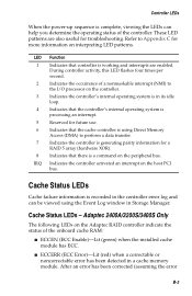
Several different controller states are indicated by the LEDs as outlined in the following sections. Additional LEDs indicate the status of the LEDs on the controller. See Appendix A for the location of the cache memory on your controller. B-1 B Controller LEDs In this Chapter ➤ LED During Power-up B-2 ➤ LEDs During Controller Idle B-2 ➤ LEDs During Controller Active B-2 ➤ Cache Status LEDs B-3 ➤ SCSI Bus Status LEDs B-4 Adaptec RAID controllers provide LEDs that let you visually monitor controller activity.
Several different controller states are indicated by the LEDs as outlined in the following sections. Additional LEDs indicate the status of the LEDs on the controller. See Appendix A for the location of the cache memory on your controller. B-1 B Controller LEDs In this Chapter ➤ LED During Power-up B-2 ➤ LEDs During Controller Idle B-2 ➤ LEDs During Controller Active B-2 ➤ Cache Status LEDs B-3 ➤ SCSI Bus Status LEDs B-4 Adaptec RAID controllers provide LEDs that let you visually monitor controller activity.

Installation Guide
Page 88
... bus activity has ceased, the controller enters the idle state. This is active, the LEDs indicate any of the affected component. Adaptec RAID Installation Guide LED During Power-up sequence, the controller passes through the following states: Condition Memory Mapped I/O Bridge Fast Idle LED Display LEDs 6 and 7 and LEDs 5 and 8 flash alternately while the controller waits for the host computer...
... bus activity has ceased, the controller enters the idle state. This is active, the LEDs indicate any of the affected component. Adaptec RAID Installation Guide LED During Power-up sequence, the controller passes through the following states: Condition Memory Mapped I/O Bridge Fast Idle LED Display LEDs 6 and 7 and LEDs 5 and 8 flash alternately while the controller waits for the host computer...
Installation Guide
Page 89
... Event Log window in Storage Manager. Cache Status LEDs - Adaptec 2400A/3200S/3400S Only The following LEDs on the Adaptec RAID controller indicate the status of the controller. Refer to perform a data transfer. 7 Indicates the controller is generating parity information for a RAID 5 array (hardware XOR). 8 Indicates that there is recorded in the controller error log and can help you determine the...
... Event Log window in Storage Manager. Cache Status LEDs - Adaptec 2400A/3200S/3400S Only The following LEDs on the Adaptec RAID controller indicate the status of the controller. Refer to perform a data transfer. 7 Indicates the controller is generating parity information for a RAID 5 array (hardware XOR). 8 Indicates that there is recorded in the controller error log and can help you determine the...
Installation Guide
Page 90
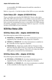
... the location of ECCERR on your controller. B-4 Adaptec RAID Installation Guide is correctable), ECCERR remains lit until the controller is enabled on the controller for the respective channels. Adaptec 3210S/3410S Only These controllers provide the ECCERR (ECC Error) cache status LED. SCSI Bus Status LEDs SCSI Bus Status LEDs - Cache Status LED - Refer to Appendix A for bus termination. I TRMPWR-A, TRMPWR...
... the location of ECCERR on your controller. B-4 Adaptec RAID Installation Guide is correctable), ECCERR remains lit until the controller is enabled on the controller for the respective channels. Adaptec 3210S/3410S Only These controllers provide the ECCERR (ECC Error) cache status LED. SCSI Bus Status LEDs SCSI Bus Status LEDs - Cache Status LED - Refer to Appendix A for bus termination. I TRMPWR-A, TRMPWR...

Installation Guide
Page 91
B-5 Controller LEDs SCSI Bus Status LEDs - Adaptec 3410S Only The following bus status LEDs are provided: I TERMEN_A, TERMEN_B, TERMEN_C, TERMEN_D-Lit when termination is supplied by the controller for the respective channels. I TPOWER_A, TPOWER_B, TPOWER_C, TPOWER_D-Lit when termination power is enabled on the controller for the respective channels.
B-5 Controller LEDs SCSI Bus Status LEDs - Adaptec 3410S Only The following bus status LEDs are provided: I TERMEN_A, TERMEN_B, TERMEN_C, TERMEN_D-Lit when termination is supplied by the controller for the respective channels. I TPOWER_A, TPOWER_B, TPOWER_C, TPOWER_D-Lit when termination power is enabled on the controller for the respective channels.

Installation Guide
Page 93
... of motherboards that can indicate a variety of 32, 64, or 128 MB. Adaptec RAID Installation Guide The controller fails to respond and the IRQ LED (and possibly other than 128 MB of the following LED patterns occurs during startup: IRQ 6 and 7 alternating with IRQ 5 and 8... the memory module. The IRQ LED indicates that each card is not compatible with another card. This incompatibility could be because it does not support large, memory-mapped, address ranges. They emit patterns that Adaptec has tested with the Adaptec controller. Adaptec 2400A/2100S/3200S/3400S only- A...
... of motherboards that can indicate a variety of 32, 64, or 128 MB. Adaptec RAID Installation Guide The controller fails to respond and the IRQ LED (and possibly other than 128 MB of the following LED patterns occurs during startup: IRQ 6 and 7 alternating with IRQ 5 and 8... the memory module. The IRQ LED indicates that each card is not compatible with another card. This incompatibility could be because it does not support large, memory-mapped, address ranges. They emit patterns that Adaptec has tested with the Adaptec controller. Adaptec 2400A/2100S/3200S/3400S only- A...

Installation Guide
Page 94
... the default settings and reconfigure the RAID. C-3 Troubleshooting The controller fails to respond and various IRQ LEDs in the controller. Pressing Ctrl+A to Appendix D. This LED pattern indicates an internal microprocessor error occurred in the 1-4 range flash once per second. This prevents the Adaptec controller from a drive that a drive attached to an Adaptec controller will be the boot drive...
... the default settings and reconfigure the RAID. C-3 Troubleshooting The controller fails to respond and various IRQ LEDs in the controller. Pressing Ctrl+A to Appendix D. This LED pattern indicates an internal microprocessor error occurred in the 1-4 range flash once per second. This prevents the Adaptec controller from a drive that a drive attached to an Adaptec controller will be the boot drive...

Installation Guide
Page 95
... procedure. C-4 If you require access to disk drives connected to the Adaptec controller during the boot process, set Bootable Devices to Appendix D. After updating the Adaptec controller firmware or BIOS and restarting, LEDs 1 and 5 or 2 and 5 flash once per second. You ...an upgrade of a drive. The floppy disk drive cannot be accessed after installing an Adaptec controller. Adaptec RAID Installation Guide The Adaptec controller BIOS reports a drive as a disk instead of the controller BIOS only, pressing Ctrl+A at the system prompt displays the message Card not configurable....
... procedure. C-4 If you require access to disk drives connected to the Adaptec controller during the boot process, set Bootable Devices to Appendix D. After updating the Adaptec controller firmware or BIOS and restarting, LEDs 1 and 5 or 2 and 5 flash once per second. You ...an upgrade of a drive. The floppy disk drive cannot be accessed after installing an Adaptec controller. Adaptec RAID Installation Guide The Adaptec controller BIOS reports a drive as a disk instead of the controller BIOS only, pressing Ctrl+A at the system prompt displays the message Card not configurable....

Installation Guide
Page 97
.... 3 Power ON the system and wait until the LEDs 3, 5, 7, and 8 on the controller begin flashing. 4 Power OFF the system and remove the jumper. 5 Restart the system. D-2 If this happens, you need to the Adaptec splash screen. Refer to their setup parameters even when ...powered OFF. If the system fails to boot, refer to Appendix C for the location of nonvolatile memory (NVRAM). Adaptec RAID Installation Guide NVRAM Reset Adaptec RAID controllers retain their default settings by following these steps: 1 Power OFF the system. 2 Install a jumper on the NVRAM reset jumper...
.... 3 Power ON the system and wait until the LEDs 3, 5, 7, and 8 on the controller begin flashing. 4 Power OFF the system and remove the jumper. 5 Restart the system. D-2 If this happens, you need to the Adaptec splash screen. Refer to their setup parameters even when ...powered OFF. If the system fails to boot, refer to Appendix C for the location of nonvolatile memory (NVRAM). Adaptec RAID Installation Guide NVRAM Reset Adaptec RAID controllers retain their default settings by following these steps: 1 Power OFF the system. 2 Install a jumper on the NVRAM reset jumper...