Veriton 7600G
Page 4
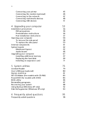
... 57 Opening your computer 58 To remove the side panel 58 To replace the side panel 59 Internal components 61 System boards 62 Mainboard layout 62 Audio board 66 Upgrading your computer 67 Installing additional memory 67 Replacing the hard disk 69 Installing an expansion card 71... 5 System utilities 75 Acrobat Reader 79 Acer LANScope (optional) 80 Norton AntiVirus 81 NTI CD-Maker (for models with CD-RW) 83 PowerDVD (for models with DVD) 85 ...
... 57 Opening your computer 58 To remove the side panel 58 To replace the side panel 59 Internal components 61 System boards 62 Mainboard layout 62 Audio board 66 Upgrading your computer 67 Installing additional memory 67 Replacing the hard disk 69 Installing an expansion card 71... 5 System utilities 75 Acrobat Reader 79 Acer LANScope (optional) 80 Norton AntiVirus 81 NTI CD-Maker (for models with CD-RW) 83 PowerDVD (for models with DVD) 85 ...

Veriton 7600G
Page 67
Component 1 5.25-inch drive bays (three bays) 2 3.5-inch drive bays (two bays) 3 Daughterboard 4 Mainboard see note 5 Hard disk 6 Expansion slots 7 Power supply Note: The mainboard model shown in the figure above may not be exactly the same with the one found in your computer looks like once you remove the side panel: No. 61 Internal components The figure below shows what your computer.
Component 1 5.25-inch drive bays (three bays) 2 3.5-inch drive bays (two bays) 3 Daughterboard 4 Mainboard see note 5 Hard disk 6 Expansion slots 7 Power supply Note: The mainboard model shown in the figure above may not be exactly the same with the one found in your computer looks like once you remove the side panel: No. 61 Internal components The figure below shows what your computer.

Veriton 7600G
Page 68
62 System boards 4 Upgrading your computer Mainboard layout The mainboard becomes accessible once you open your Veriton 7600 series computer model. Refer to the section below for the corresponding mainboard layout of your computer.
62 System boards 4 Upgrading your computer Mainboard layout The mainboard becomes accessible once you open your Veriton 7600 series computer model. Refer to the section below for the corresponding mainboard layout of your computer.

Veriton 7600G
Page 71
Label JFP1 JKBMS1 JPW1 JRECOVER LPT1 PCI1 to PCI3 SATA1 SATA2 SER1 U10 U19 USB1 USB2 USB3 USB4 VGA1 65 Component HDD LED, Power LED connector Power button and Reset switch controller PS/2 mouse (upper) and keyboard (lower) ports Power connector (12V power) One Touch Recovery button connector Parallel/Printer port PCI slots 1 to 3 Serial HDD connectors Serial port Northbridge Southbridge USB ports Front USB 2.0 connector or Unused Front USB 2.0 connector or Unused USB ports Monitor port (VT7600G only) Note: For the location of the AGP slot on the Veriton 7600! mainboard, see page 61.
Label JFP1 JKBMS1 JPW1 JRECOVER LPT1 PCI1 to PCI3 SATA1 SATA2 SER1 U10 U19 USB1 USB2 USB3 USB4 VGA1 65 Component HDD LED, Power LED connector Power button and Reset switch controller PS/2 mouse (upper) and keyboard (lower) ports Power connector (12V power) One Touch Recovery button connector Parallel/Printer port PCI slots 1 to 3 Serial HDD connectors Serial port Northbridge Southbridge USB ports Front USB 2.0 connector or Unused Front USB 2.0 connector or Unused USB ports Monitor port (VT7600G only) Note: For the location of the AGP slot on the Veriton 7600! mainboard, see page 61.

Veriton 7600G
Page 72
66 4 Upgrading your computer Audio board The audio board that follows. connects to the JUSB1 of the!mainboard USB Connector - However, you can not use both of the mainboard Standard audio connector -unsed Microphone-in jack Audio out port Note: The system has two microphone-in front and disables the one at the...
66 4 Upgrading your computer Audio board The audio board that follows. connects to the JUSB1 of the!mainboard USB Connector - However, you can not use both of the mainboard Standard audio connector -unsed Microphone-in jack Audio out port Note: The system has two microphone-in front and disables the one at the...

Veriton 7600G
Page 73
... or PC3200/DDR400 modules in your dealer or a qualified service technician for assistance. Installing additional memory The four 184-pin sockets on the mainboard support Double Data Rate (DDR) Synchronous Dynamic Random Access Memory (SDRAM)-type DIMMs. You may not be exactly the same with different capacities...these upgrades yourself. Contact your computer are upgradeable such as the memory, the hard disk, the CPU and the expansion cards. Note: The mainboard model shown in the following figures may install 128-MB, 256-MB, 512-MB or 1-GB DIMMs for a maximum memory capacity of 4 ...
... or PC3200/DDR400 modules in your dealer or a qualified service technician for assistance. Installing additional memory The four 184-pin sockets on the mainboard support Double Data Rate (DDR) Synchronous Dynamic Random Access Memory (SDRAM)-type DIMMs. You may not be exactly the same with different capacities...these upgrades yourself. Contact your computer are upgradeable such as the memory, the hard disk, the CPU and the expansion cards. Note: The mainboard model shown in the following figures may install 128-MB, 256-MB, 512-MB or 1-GB DIMMs for a maximum memory capacity of 4 ...

Veriton 7600G
Page 74
... DIMM but it again. Turn the DDR DIMM around and try to ensure proper installation. 68 4 Upgrading your computer 3 Press the holding clips on the mainboard. 2 Align the DDR DIMM with the socket (a).
... DIMM but it again. Turn the DDR DIMM around and try to ensure proper installation. 68 4 Upgrading your computer 3 Press the holding clips on the mainboard. 2 Align the DDR DIMM with the socket (a).

Veriton 7600G
Page 77
Note: Make sure that the other ends of the disk cables are securely connected to their corresponding connectors on the mainboard. 3 Remove the screw that holds the bracket to the computer. Save the screw. Installing an expansion card To install an expansion card: 1 Remove the side panel (see page 58). 2 Locate an empty PCI slot on the mainboard. 6 Replace the side panel (see page 59). 71 5 Secure it with the four screws you removed earlier.
Note: Make sure that the other ends of the disk cables are securely connected to their corresponding connectors on the mainboard. 3 Remove the screw that holds the bracket to the computer. Save the screw. Installing an expansion card To install an expansion card: 1 Remove the side panel (see page 58). 2 Locate an empty PCI slot on the mainboard. 6 Replace the side panel (see page 59). 71 5 Secure it with the four screws you removed earlier.
Veriton 7600G
Page 117
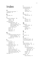
.../suspend key email 20 suspend 20 web browser 20 K keyboard 18 application key 25 L lock keys Caps Lock 23 Num Lock 23 Scroll Lock 23 M mainboard Veriton 7600G 63 multimedia key forward 21 play/pause 21 stop 21 N NTI 83 P PowerDVD 85 R rear panel 16 recovering your system 88 remove the side panel...
.../suspend key email 20 suspend 20 web browser 20 K keyboard 18 application key 25 L lock keys Caps Lock 23 Num Lock 23 Scroll Lock 23 M mainboard Veriton 7600G 63 multimedia key forward 21 play/pause 21 stop 21 N NTI 83 P PowerDVD 85 R rear panel 16 recovering your system 88 remove the side panel...

