Veriton 5500/7500 Service Guide
Page 7
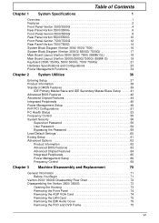
... 1 System Specifications 1 Overview 1 Features 2 Front Panel-Veriton 3500/3500G 4 Rear Panel-Veriton 3500/3500G 6 Front Panel-Veriron 5500/5500G 8 Rear Panel-Veriton 5500/5500G 10 Front Panel-Veriton 7500/7500G 12 Rear Panel-Veriton 7500/7500G 14 System Block Diagram (Veriton 3500/ 5500/ 7500 16 System Block Diagram (Veriton 3500G/ 5500G/ 7500G 17 Main Board Layout (Veriton 3500/ 5500/ 7500) (S88M/ GL 18 Main Board...
... 1 System Specifications 1 Overview 1 Features 2 Front Panel-Veriton 3500/3500G 4 Rear Panel-Veriton 3500/3500G 6 Front Panel-Veriron 5500/5500G 8 Rear Panel-Veriton 5500/5500G 10 Front Panel-Veriton 7500/7500G 12 Rear Panel-Veriton 7500/7500G 14 System Block Diagram (Veriton 3500/ 5500/ 7500 16 System Block Diagram (Veriton 3500G/ 5500G/ 7500G 17 Main Board Layout (Veriton 3500/ 5500/ 7500) (S88M/ GL 18 Main Board...

Veriton 5500/7500 Service Guide
Page 8
...Sink 82 Removing and Installing the Processor 83 Removing the System Main board 84 Removing the I/O Port Bracket 84 Veriton 5500/ 5500G Disassembly Procedure Flowchart 85 Disassembling the Veriton 5500/ 5500G 86 Open the Housing Cover 86 Removing the Front Panel 86 Removing the Empty Cover 87 Removing a Dummy... Procedure Flowchart 98 Disassembling the Veriton 7500/ 7500G 99 Opening the Housing 99 Removing the Front Panel 99 Removing the Modem Card 100 Removing the AGP VGA Card 100 Removing the USB/ Audio Board 101 Removing the DVD-ROM and CD-RW Drive 102 Removing the Floppy Disk...
...Sink 82 Removing and Installing the Processor 83 Removing the System Main board 84 Removing the I/O Port Bracket 84 Veriton 5500/ 5500G Disassembly Procedure Flowchart 85 Disassembling the Veriton 5500/ 5500G 86 Open the Housing Cover 86 Removing the Front Panel 86 Removing the Empty Cover 87 Removing a Dummy... Procedure Flowchart 98 Disassembling the Veriton 7500/ 7500G 99 Opening the Housing 99 Removing the Front Panel 99 Removing the Modem Card 100 Removing the AGP VGA Card 100 Removing the USB/ Audio Board 101 Removing the DVD-ROM and CD-RW Drive 102 Removing the Floppy Disk...
Veriton 5500/7500 Service Guide
Page 11
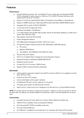
...-bit graphics accelerator installed in the AGP Pro card slot (AGP slot: not available for Veriton 3500G, 5500G and 7500G only) ! Liquid crystal display (LCD) support (optional) ! By default, your system ...ROM, DVD-ROM or CD-RW drive ! 1.5 V AGP interface with Plug and Play function 2 Veriton 3500/5500/7500 High capacity, Enhanced-IDE hard disk ! Two high-speed NS 16C550-compatible serial ports ! ... An additional AGP card 1.5V slot, supports 1X, 2X and 4X ! 3-D quality audio system via onboard audio controller ! Ultra DMA/33, Ultra DMA/66 & Ultra DMA/100 modes ! Intel ...
...-bit graphics accelerator installed in the AGP Pro card slot (AGP slot: not available for Veriton 3500G, 5500G and 7500G only) ! Liquid crystal display (LCD) support (optional) ! By default, your system ...ROM, DVD-ROM or CD-RW drive ! 1.5 V AGP interface with Plug and Play function 2 Veriton 3500/5500/7500 High capacity, Enhanced-IDE hard disk ! Two high-speed NS 16C550-compatible serial ports ! ... An additional AGP card 1.5V slot, supports 1X, 2X and 4X ! 3-D quality audio system via onboard audio controller ! Ultra DMA/33, Ultra DMA/66 & Ultra DMA/100 modes ! Intel ...
Veriton 5500/7500 Service Guide
Page 26
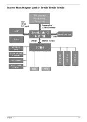
System Block Diagram (Veriton 3500G/ 5500G/ 7500G) AGP VGA AGP 4X/ 2X 1.5V signal Willamette/ Northwood Processor Scaleable Bus 3.2GB/s (4.25GB/s) Brookdale-G GMCH DDDDRR-2-26666/ /220000 2.12GB/s 266MB/s 8-Bit Hub Interface 6 USB 2.0 ports 2 ATA 100 IDE Channels LAN Connect AC97' Audio CODEC ICH4 SIO FWH PCI Slot PCI Slot PCI Slot Chapter 1 17
System Block Diagram (Veriton 3500G/ 5500G/ 7500G) AGP VGA AGP 4X/ 2X 1.5V signal Willamette/ Northwood Processor Scaleable Bus 3.2GB/s (4.25GB/s) Brookdale-G GMCH DDDDRR-2-26666/ /220000 2.12GB/s 266MB/s 8-Bit Hub Interface 6 USB 2.0 ports 2 ATA 100 IDE Channels LAN Connect AC97' Audio CODEC ICH4 SIO FWH PCI Slot PCI Slot PCI Slot Chapter 1 17
Veriton 5500/7500 Service Guide
Page 29
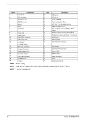
... (Veriton 3500G/ 5500G/ 7500G) NOTE: ***: not for Brookdale G only) Power Connector (+12V Line-in (upper), Line-out(middle), Mic-in Connecto Audio for Daughter Board AGP Slot***(for Brookdale-GL 20 Veriton 3500/5500/7500 Label 1 2 3 4 5 6 7 Game Port Component FDD Connector IDE 2 Connector IDE 1 Connector Battery FWH Serial IRQ 8 Power LED 9 Power Button 10 Audio FPIO... 3-pin Fan CPU Connector 34 Memory Slot 1 35 Memory Slot 2 36 Power Connector 37 COM 38 SMSC LPC47M192 NOTE: *: default setting NOTE: **: Intel 845 GL (Veriton 3500/ 5500/ 7500);
... (Veriton 3500G/ 5500G/ 7500G) NOTE: ***: not for Brookdale G only) Power Connector (+12V Line-in (upper), Line-out(middle), Mic-in Connecto Audio for Daughter Board AGP Slot***(for Brookdale-GL 20 Veriton 3500/5500/7500 Label 1 2 3 4 5 6 7 Game Port Component FDD Connector IDE 2 Connector IDE 1 Connector Battery FWH Serial IRQ 8 Power LED 9 Power Button 10 Audio FPIO... 3-pin Fan CPU Connector 34 Memory Slot 1 35 Memory Slot 2 36 Power Connector 37 COM 38 SMSC LPC47M192 NOTE: *: default setting NOTE: **: Intel 845 GL (Veriton 3500/ 5500/ 7500);
Veriton 5500/7500 Service Guide
Page 106
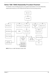
CD-RW/ DVD-ROM CPU Fan Sink CPU Chapter 3 98 Main Unit Left Panel FDD Module RTC Battery Right Panel AGP VGA Card Modem Card HDD Module DIMM Front Panel Main Board Power Supply USB/Audio Board Intrusion Alarm Cable LED Activity Indicators W/ Power Swtich Cable Module NOTE: There is no AGP VGA Slot for Veriton 7500. Veriton 7500/ 7500G Disassembly Procedure Flowchart The flowchart on the succeeding page gives you a graphical representation on the entire disassembly sequence and instructs you on the components that need to be removed during servicing.
CD-RW/ DVD-ROM CPU Fan Sink CPU Chapter 3 98 Main Unit Left Panel FDD Module RTC Battery Right Panel AGP VGA Card Modem Card HDD Module DIMM Front Panel Main Board Power Supply USB/Audio Board Intrusion Alarm Cable LED Activity Indicators W/ Power Swtich Cable Module NOTE: There is no AGP VGA Slot for Veriton 7500. Veriton 7500/ 7500G Disassembly Procedure Flowchart The flowchart on the succeeding page gives you a graphical representation on the entire disassembly sequence and instructs you on the components that need to be removed during servicing.
Veriton 5500/7500 Service Guide
Page 135
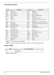
Function and settings 127 Veriton 3500/5500/7500 Connector Description Label CN6 CN9 CN12 CN13 BT1 U24 CN23 Game Port Component FDD Connector IDE 2 Connector IDE 1 Connector Battery FWH Serial IRQ CN26 CN21 CN25 CN19 JP2 CN20 CN22 CN24 U21 CN18 U14 SL1 Power LED Power Button Audio FPIO Connector LAN Activity LED ...3-pin Fan CPU Connector Memory Slot 1 Memory Slot 2 Power Connector COM SMSC NOTE: There is no AGP VGA slot for S88M/GL. Intel 845G (Veriton 3500G/ 5500G/ 7500G) Jumper Setting Jumper JP2 1-2 Normal* 2-3 Clear CMOS NOTE: *: Default Settings. NOTE: *: Intel 845 GL...
Function and settings 127 Veriton 3500/5500/7500 Connector Description Label CN6 CN9 CN12 CN13 BT1 U24 CN23 Game Port Component FDD Connector IDE 2 Connector IDE 1 Connector Battery FWH Serial IRQ CN26 CN21 CN25 CN19 JP2 CN20 CN22 CN24 U21 CN18 U14 SL1 Power LED Power Button Audio FPIO Connector LAN Activity LED ...3-pin Fan CPU Connector Memory Slot 1 Memory Slot 2 Power Connector COM SMSC NOTE: There is no AGP VGA slot for S88M/GL. Intel 845G (Veriton 3500G/ 5500G/ 7500G) Jumper Setting Jumper JP2 1-2 Normal* 2-3 Clear CMOS NOTE: *: Default Settings. NOTE: *: Intel 845 GL...


