
Veriton 5200
Page 5
...power supply cord set (provided in performance, indicating a need for this unit. Keep them in damage and will often require extensive work by the operating instructions since improper adjustment of other risks. Use of another battery may explode if not handled properly. Year 2000 compliance statement The Veriton 5200... computer carries the "Hardware NSTL Tested Year 2000 Compliant" logo, which certifies that are followed. For more details, check the Acer Year 2000 Resource Center at http:// global.acer.com/service/pcy2000.html e...
...power supply cord set (provided in performance, indicating a need for this unit. Keep them in damage and will often require extensive work by the operating instructions since improper adjustment of other risks. Use of another battery may explode if not handled properly. Year 2000 compliance statement The Veriton 5200... computer carries the "Hardware NSTL Tested Year 2000 Compliant" logo, which certifies that are followed. For more details, check the Acer Year 2000 Resource Center at http:// global.acer.com/service/pcy2000.html e...

Veriton 5200
Page 20
12 Rear panel Your computer's rear panel consists of the following: 2 System tour Label Icon 1 2 3 4 5 6 7 Color Green Description Power supply Main power switch Power cable socket Voltage selector switch PS/2 mouse port Purple Black PS/2 keyboard port USB ports
12 Rear panel Your computer's rear panel consists of the following: 2 System tour Label Icon 1 2 3 4 5 6 7 Color Green Description Power supply Main power switch Power cable socket Voltage selector switch PS/2 mouse port Purple Black PS/2 keyboard port USB ports

Veriton 5200
Page 59
Component 1 3.5-inch drive bay 2 5.25-inch drive bay 3 Power supply 4 Metal brackets (hard disk drive frame) 5 Expansion slots 6 Mainboard 51 Internal components The figure below shows what your computer looks like once you remove the cover: No.
Component 1 3.5-inch drive bay 2 5.25-inch drive bay 3 Power supply 4 Metal brackets (hard disk drive frame) 5 Expansion slots 6 Mainboard 51 Internal components The figure below shows what your computer looks like once you remove the cover: No.
Veriton 5200 Service Guide
Page 7
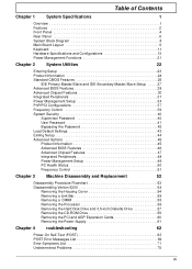
... BIOS Features 46 Advanced Chipset Features 47 Integrated Peripherals 48 Power Management Setup 49 PC Health Status 50 Frequency Control 51 Chapter 3 Machine Disassembly and Replacement 52 Disassembly Procedure Flowchart 53 Disassembling Veriton 5200 54 Removing the Housing Cover 54 Removing a Link Bar ...55 Removing a DIMM 55 Removing the Processor 56 Removing the Hard Disk Drive and 3.5-inch Diskette Drive 57 Removing the CD-ROM Drive 59 Removing the PCI and AGP Expansion Cards 60 Removing the Power Supply...
... BIOS Features 46 Advanced Chipset Features 47 Integrated Peripherals 48 Power Management Setup 49 PC Health Status 50 Frequency Control 51 Chapter 3 Machine Disassembly and Replacement 52 Disassembly Procedure Flowchart 53 Disassembling Veriton 5200 54 Removing the Housing Cover 54 Removing a Link Bar ...55 Removing a DIMM 55 Removing the Processor 56 Removing the Hard Disk Drive and 3.5-inch Diskette Drive 57 Removing the CD-ROM Drive 59 Removing the PCI and AGP Expansion Cards 60 Removing the Power Supply...

Veriton 5200 Service Guide
Page 15
Rear Panel Label 1 2 3 4 Icon Color Green Description Power Supply Power Switch Power Cord Socket PS/2 Mouse Port 5 Purple PS/2 Keyboard Port 6 Black USB Ports 7 White Network Port 8 Teal or Turquoise Serial Port 9 Blue CRT/LCD Monitor Port 10 Burgundy Parallel/Printer Port 6 Chapter 1
Rear Panel Label 1 2 3 4 Icon Color Green Description Power Supply Power Switch Power Cord Socket PS/2 Mouse Port 5 Purple PS/2 Keyboard Port 6 Black USB Ports 7 White Network Port 8 Teal or Turquoise Serial Port 9 Blue CRT/LCD Monitor Port 10 Burgundy Parallel/Printer Port 6 Chapter 1

Veriton 5200 Service Guide
Page 29
Mechanical Specifications Item Weight One 3.5 FDD and one 3.5 HDD (without packing) Specification Depends on local configuration Switching Power Supply 200W (165W option) A-1 Inpute frequency 50Hz 60Hz Normal Frequency 47Hz to 53Hz 57Hz to 63Hz Frequency Variation Range A-2 Input voltage Nominal Voltage 100 - 120 VRMS ... 1 Measure at line input 90 VRMS and maximum load condition Output Requirements +5V +12V -12V +3.3V -5V +5Vaux +-5% +-5% +-10% +-5% +-10% +-5% Regulation NOTE: 1. +5V & +3.3V total power is 200W or 235W power supply) ! This :4A: includes the oultet...
Mechanical Specifications Item Weight One 3.5 FDD and one 3.5 HDD (without packing) Specification Depends on local configuration Switching Power Supply 200W (165W option) A-1 Inpute frequency 50Hz 60Hz Normal Frequency 47Hz to 53Hz 57Hz to 63Hz Frequency Variation Range A-2 Input voltage Nominal Voltage 100 - 120 VRMS ... 1 Measure at line input 90 VRMS and maximum load condition Output Requirements +5V +12V -12V +3.3V -5V +5Vaux +-5% +-5% +-10% +-5% +-10% +-5% Regulation NOTE: 1. +5V & +3.3V total power is 200W or 235W power supply) ! This :4A: includes the oultet...
Veriton 5200 Service Guide
Page 62
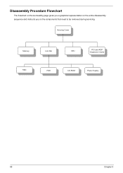
Housing Cover Memory Link Bar CPU PCI and AGP Expansion Cards HDD FDD CD-ROM Power Supply 53 Chapter 3 Disassembly Procedure Flowchart The flowchart on the succeeding page gives you a graphical representation on the entire disassembly sequence and instructs you on the components that need to be removed during servicing.
Housing Cover Memory Link Bar CPU PCI and AGP Expansion Cards HDD FDD CD-ROM Power Supply 53 Chapter 3 Disassembly Procedure Flowchart The flowchart on the succeeding page gives you a graphical representation on the entire disassembly sequence and instructs you on the components that need to be removed during servicing.

Veriton 5200 Service Guide
Page 70
See "Removing a Link Bar" on the system, BIOS automatically detects and assigns resources to the housing and pull out the power supply. 61 Chapter 3 NOTE: When you turn on page 55 3. Remove the four screws that hold the power supply to the PCI devices. Removing the Power Supply 1. See "Removing the Housing Cover" on page 54 2.
See "Removing a Link Bar" on the system, BIOS automatically detects and assigns resources to the housing and pull out the power supply. 61 Chapter 3 NOTE: When you turn on page 55 3. Remove the four screws that hold the power supply to the PCI devices. Removing the Power Supply 1. See "Removing the Housing Cover" on page 54 2.
Veriton 5200 Service Guide
Page 78
...the memory map for a description of your system to None. Also check the power supply voltages if you assumed the system would boot from the hard drive, make sure the controller is ...inserted correctly and all power supply voltages, switch, and jumper settings before you did receive a POST error message, use "POST... change . NOTE: When you have deemed it necessary to replace an FRU, and have a "system no-power" condition. NOTE: Check all cables are pressed during the boot. Insert system disk into Drive (A:)and presse....
...the memory map for a description of your system to None. Also check the power supply voltages if you assumed the system would boot from the hard drive, make sure the controller is ...inserted correctly and all power supply voltages, switch, and jumper settings before you did receive a POST error message, use "POST... change . NOTE: When you have deemed it necessary to replace an FRU, and have a "system no-power" condition. NOTE: Check all cables are pressed during the boot. Insert system disk into Drive (A:)and presse....

Veriton 5200 Service Guide
Page 80
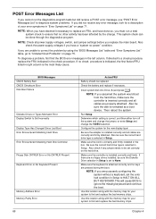
.... Diskette/IDE drive connection/cables 2. Main board Diskette drive does not work , then replace a good fan. 3. Diskette drive. 5. See "Power Management" in the DIMM sockets properly, then reboot the system. 2. If the reading shows normal, but the fan still does not work . .... 2. Main board and Memory NOTE: Ensure the memory modules are installed properly and the contact leads are mismatched. 1. System works but power supply fan runs. 1. Diskette. 2. Its reading should be +12Vdc. Main board. Main board Diskette Drive NOTE: Ensure the diskette drive is...
.... Diskette/IDE drive connection/cables 2. Main board Diskette drive does not work , then replace a good fan. 3. Diskette drive. 5. See "Power Management" in the DIMM sockets properly, then reboot the system. 2. If the reading shows normal, but the fan still does not work . .... 2. Main board and Memory NOTE: Ensure the memory modules are installed properly and the contact leads are mismatched. 1. System works but power supply fan runs. 1. Diskette. 2. Its reading should be +12Vdc. Main board. Main board Diskette Drive NOTE: Ensure the diskette drive is...
Veriton 5200 Service Guide
Page 83
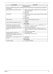
... is the same as the setting in BIOS Setup of the machine, just above the connector for the printer. No system power, or power supply fan is properly installed. Printing failed. 1. Loop-back. 3. Ensure the printer driver is not running. 1. Keyboard Some or all keys on the system. 1. in BIOS ...
... is the same as the setting in BIOS Setup of the machine, just above the connector for the printer. No system power, or power supply fan is properly installed. Printing failed. 1. Loop-back. 3. Ensure the printer driver is not running. 1. Keyboard Some or all keys on the system. 1. in BIOS ...

Veriton 5200 Service Guide
Page 84
...one at a time: 10. Check all main board jumper positions and switch settings. 6. Non-Acer devices ! Hard disk drive ! If the voltages are correct, remove or disconnect the following steps: 2. Power off the system unit. 3. If the jumpers, switches and voltage settings are correct continue with ... an error message is listed in setup. 5. If you find the failing device or adapter. 75 Chapter 4 Check the power supply voltages. Check all cables and connectors for proper installation. 9. Check all adapter card jumper positions. 7. External devices ! Diskette drive ! DIMM...
...one at a time: 10. Check all main board jumper positions and switch settings. 6. Non-Acer devices ! Hard disk drive ! If the voltages are correct, remove or disconnect the following steps: 2. Power off the system unit. 3. If the jumpers, switches and voltage settings are correct continue with ... an error message is listed in setup. 5. If you find the failing device or adapter. 75 Chapter 4 Check the power supply voltages. Check all cables and connectors for proper installation. 9. Check all adapter card jumper positions. 7. External devices ! Diskette drive ! DIMM...
Veriton 5200 Service Guide
Page 107
...port 7 B Basic level 23 BIOS Setup 22 Entering Setup 23 Setup Utility 23 BIOS Utility Disk Drives 25 Exiting Setup 44 Load Default Settings 43 Power Management 34 Product Information 24 System Security 40 Block Diagram 8 C Cache Memory 14 size 14 speed 14 Chipsets 19 CMOS Setup 22 Compatibility Test ... removing 55, 56 CPU upgrade removing 55, 56 CRT Monitor port 7 Current 20 Index Index D Device Standby Mode 21 disassembly CD-ROM Drive 59 Power Supply 61 Disk Drives 25 IDE primary channel master 25 IDE primary channel slave 25 IDE secondary channel master 25 IDE secondary channel slave 25 DRQ...
...port 7 B Basic level 23 BIOS Setup 22 Entering Setup 23 Setup Utility 23 BIOS Utility Disk Drives 25 Exiting Setup 44 Load Default Settings 43 Power Management 34 Product Information 24 System Security 40 Block Diagram 8 C Cache Memory 14 size 14 speed 14 Chipsets 19 CMOS Setup 22 Compatibility Test ... removing 55, 56 CPU upgrade removing 55, 56 CRT Monitor port 7 Current 20 Index Index D Device Standby Mode 21 disassembly CD-ROM Drive 59 Power Supply 61 Disk Drives 25 IDE primary channel master 25 IDE primary channel slave 25 IDE secondary channel master 25 IDE secondary channel slave 25 DRQ...
Veriton 5200 Service Guide
Page 108
... replacing HDD 57 RMA 78 Routing Map 17 S Security 40 Serial Port 16 Serial port 6 socket memory 14 Socket 370 13 Suspend Mode 21 Switching Power Supply 102W 20 Symptoms List Audio 73 CD/DVD-ROM Drive 72 Diskette Drive 71 Keyboard 74 Memory 71 Modem 73 Monitor 73 Other 74 Parallel... Port 74 Power Supply 74 Processor / Processor Fan 71 Real-Time Clock 72 Serial Port 74 System Board 71 Video 73 System 22 System Specifications 1, 85 design 3 Index
... replacing HDD 57 RMA 78 Routing Map 17 S Security 40 Serial Port 16 Serial port 6 socket memory 14 Socket 370 13 Suspend Mode 21 Switching Power Supply 102W 20 Symptoms List Audio 73 CD/DVD-ROM Drive 72 Diskette Drive 71 Keyboard 74 Memory 71 Modem 73 Monitor 73 Other 74 Parallel... Port 74 Power Supply 74 Processor / Processor Fan 71 Real-Time Clock 72 Serial Port 74 System Board 71 Video 73 System 22 System Specifications 1, 85 design 3 Index


