TravelMate 660 Service Guide
Page 7
... 35 Main 36 System Devices 38 Security 39 Boot 43 Exit 44 BIOS Flash Utility 45 Chapter 3 Machine Disassembly and Replacement 47 General Information 48 Before You Begin 48 Disassembly Procedure Flowchart 49 Removing the Battery Pack 52 Removing the Optical Module/HDD Module/Wireless Lan Card and LCD ...module . .53 Removing the Optical Module 53 Removing the HDD Module 53 Removing the Wireless LAN Card 53 Removing the LCD Module 54 Disassembling the Main Unit 55 Remove the function key board and the keyboard 55 Separate the main unit into the logic upper and the logic lower...
... 35 Main 36 System Devices 38 Security 39 Boot 43 Exit 44 BIOS Flash Utility 45 Chapter 3 Machine Disassembly and Replacement 47 General Information 48 Before You Begin 48 Disassembly Procedure Flowchart 49 Removing the Battery Pack 52 Removing the Optical Module/HDD Module/Wireless Lan Card and LCD ...module . .53 Removing the Optical Module 53 Removing the HDD Module 53 Removing the Wireless LAN Card 53 Removing the LCD Module 54 Disassembling the Main Unit 55 Remove the function key board and the keyboard 55 Separate the main unit into the logic upper and the logic lower...
TravelMate 660 Service Guide
Page 8
Table of Contents Disassembling the Optical Drive Module 61 Chpater 4 Troubleshooting 63 System Check Procedures 64 External Diskette Drive Check 64 External CD-ROM Drive Check 64 Keyboard or ... Intermittent Problems 74 Undetermined Problems 75 Chpater 5 Jumper and Connector Locations 77 Top View 77 Bottom View 79 Chapter 6 FRU (Field Replaceable Unit) List 81 TravelMate 660 Series 92 Appendix A Model Definition and Configuration 92 Main Features 93 Appendix B Test Compatible Components 95 Microsoft® Windows® XP Pro Environment Test 96...
Table of Contents Disassembling the Optical Drive Module 61 Chpater 4 Troubleshooting 63 System Check Procedures 64 External Diskette Drive Check 64 External CD-ROM Drive Check 64 Keyboard or ... Intermittent Problems 74 Undetermined Problems 75 Chpater 5 Jumper and Connector Locations 77 Top View 77 Bottom View 79 Chapter 6 FRU (Field Replaceable Unit) List 81 TravelMate 660 Series 92 Appendix A Model Definition and Configuration 92 Main Features 93 Appendix B Test Compatible Components 95 Microsoft® Windows® XP Pro Environment Test 96...

TravelMate 660 Service Guide
Page 55
..., group the screws with the corresponding components to avoid mismatch when putting back the components. Chapter 3 47 To disassemble the computer, you remove the stripe cover, please be careful not to scrape the cover. When you need the following tools: T Wrist grounding strap and ... driver T Philips screw driver T Flat head screwdriver T Plastic flat head screw driver T Hex screw driver T Tweezers NOTE: The screws for maintenance and troubleshooting. Chapter 3 Machine Disassembly and Replacement This chapter contains step-by-step procedures on how to...
..., group the screws with the corresponding components to avoid mismatch when putting back the components. Chapter 3 47 To disassemble the computer, you remove the stripe cover, please be careful not to scrape the cover. When you need the following tools: T Wrist grounding strap and ... driver T Philips screw driver T Flat head screwdriver T Plastic flat head screw driver T Hex screw driver T Tweezers NOTE: The screws for maintenance and troubleshooting. Chapter 3 Machine Disassembly and Replacement This chapter contains step-by-step procedures on how to...
TravelMate 660 Service Guide
Page 56
NOTE: TravelMate 660 series product uses mylar or tape to fasten the FFC/FPC/connectors/cable, you may need to the system and all power and signal cables from the system. 3. Remove the battery pack. Unplug the AC adapter and all peripherals. 2. General Information Before You Begin Before proceeding with the disassembly procedure, make sure that you disconnect different FFC/FPC/connectors. 48 Chapter 3 Turn off the power to tear the tape or mylar before you do the following: 1.
NOTE: TravelMate 660 series product uses mylar or tape to fasten the FFC/FPC/connectors/cable, you may need to the system and all power and signal cables from the system. 3. Remove the battery pack. Unplug the AC adapter and all peripherals. 2. General Information Before You Begin Before proceeding with the disassembly procedure, make sure that you disconnect different FFC/FPC/connectors. 48 Chapter 3 Turn off the power to tear the tape or mylar before you do the following: 1.
TravelMate 660 Service Guide
Page 57
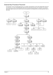
...Ax4 Hx1 Hx1 Main Board CPU Dimm Dx3 4-in that need to remove the system board, you must first remove the keyboard, then disassemble the inside assembly frame in -1 Card Rearder Fx2 Smart Card Reader Hx1 Top Cover Shielding Tx2 HDD Bracket Hx2 Modem/ Bluetooth Combo ...Card Ex4 Thermal Module Antenna Line Modem Cable Chapter 3 49 Disassembly Procedure Flowchart The flowchart on the succeeding page gives you a graphic representation on the entire disassembly sequence and instructs you on the components that order.
...Ax4 Hx1 Hx1 Main Board CPU Dimm Dx3 4-in that need to remove the system board, you must first remove the keyboard, then disassemble the inside assembly frame in -1 Card Rearder Fx2 Smart Card Reader Hx1 Top Cover Shielding Tx2 HDD Bracket Hx2 Modem/ Bluetooth Combo ...Card Ex4 Thermal Module Antenna Line Modem Cable Chapter 3 49 Disassembly Procedure Flowchart The flowchart on the succeeding page gives you a graphic representation on the entire disassembly sequence and instructs you on the components that order.
TravelMate 660 Service Guide
Page 63
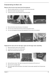
... the logic lower assembly 1. Remove the three screws that secure the keyboard. 5. Unscrew the three screws holding the function key board. 4. Disconnect the touchpad cable. 6. Disassembling the Main Unit Remove the function key board and the keyboard 1. Take the wireless antenna out of the hook on the function key board. 2.
... the logic lower assembly 1. Remove the three screws that secure the keyboard. 5. Unscrew the three screws holding the function key board. 4. Disconnect the touchpad cable. 6. Disassembling the Main Unit Remove the function key board and the keyboard 1. Take the wireless antenna out of the hook on the function key board. 2.
TravelMate 660 Service Guide
Page 64
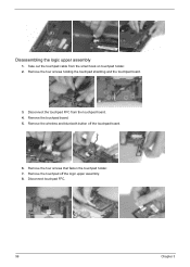
Disassembling the logic upper assembly 1. Remove the wireless and bluetooth button off the logic upper assembly. 8. Remove the touchpad board. 5. Remove the touchpad off the touchpad board. 6. Take out the touchpad cable from the touchpad board. 4. Disconnect the touchpad FFC from the small hook on touchpad holder. 2. Disconnect touchpad FFC. 56 Chapter 3 Remove the four screws that fasten the touchpad holder. 7. Remove the four screws holding the touchpad shielding and the touchpad board. 3.
Disassembling the logic upper assembly 1. Remove the wireless and bluetooth button off the logic upper assembly. 8. Remove the touchpad board. 5. Remove the touchpad off the touchpad board. 6. Take out the touchpad cable from the touchpad board. 4. Disconnect the touchpad FFC from the small hook on touchpad holder. 2. Disconnect touchpad FFC. 56 Chapter 3 Remove the four screws that fasten the touchpad holder. 7. Remove the four screws holding the touchpad shielding and the touchpad board. 3.
TravelMate 660 Service Guide
Page 65
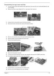
... bluetooth antenna. 8. Remove one screw that secure the thermal module. 4. Chapter 3 57 In order to take the main board off the lower case assembly. 11. Disassembling the logic lower assembly 1. Remove another screw that fasten the HDD bracket. 12. Then take out the main board from the lower case assembly, first...
... bluetooth antenna. 8. Remove one screw that secure the thermal module. 4. Chapter 3 57 In order to take the main board off the lower case assembly. 11. Disassembling the logic lower assembly 1. Remove another screw that fasten the HDD bracket. 12. Then take out the main board from the lower case assembly, first...

TravelMate 660 Service Guide
Page 67
... Remove the two screws holding the LCD to LCD panel. 5. Then remove the right and the left LCD brackets. Disconnect the LCD coaxial cable. . 10. Disassembling the LCD Module 1. Remove the six screw pad and the six screws. 2.
... Remove the two screws holding the LCD to LCD panel. 5. Then remove the right and the left LCD brackets. Disconnect the LCD coaxial cable. . 10. Disassembling the LCD Module 1. Remove the six screw pad and the six screws. 2.
TravelMate 660 Service Guide
Page 69
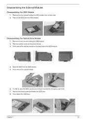
... ODD module. 4. Then detach the ODD door. Then remove the last two screws on each side. 2. Remove the three screws that fasten the ODD door. 8. Disassembling the External Modules Disassembling the HDD Module 1. Remove the two screws holding the HDD bracket; Take out the HDD from the ODD bracket...
... ODD module. 4. Then detach the ODD door. Then remove the last two screws on each side. 2. Remove the three screws that fasten the ODD door. 8. Disassembling the External Modules Disassembling the HDD Module 1. Remove the two screws holding the HDD bracket; Take out the HDD from the ODD bracket...

TravelMate 660 Service Guide
Page 71
... (Verified) Power failure. (The power indicator does not go on or stay on screen. Symptoms cannot be re-created (intermittent problems). Disassemble and assemble the unit without any problem occurs, you can perform visual inspection before you fellow this model. all components appear normal. 5. POST... or heated components; LCD display problems or others). Verify the symptoms by repeating the same operation. 3. there are indicated. Non-Acer products, prototype cards, or modified options can check the following table with the verified symptom to determine which page to go to ...
... (Verified) Power failure. (The power indicator does not go on or stay on screen. Symptoms cannot be re-created (intermittent problems). Disassemble and assemble the unit without any problem occurs, you can perform visual inspection before you fellow this model. all components appear normal. 5. POST... or heated components; LCD display problems or others). Verify the symptoms by repeating the same operation. 3. there are indicated. Non-Acer products, prototype cards, or modified options can check the following table with the verified symptom to determine which page to go to ...
TravelMate 660 Service Guide
Page 113
... 28 CPU core voltage 23 package 23 type 23 D DIMM 23 Combinations 24 external 53 package 23 removing 53 Speed 23 voltage 23 Index Index Disassembly Battery Pack 50 CD-ROM/DVD-ROM Module 55 Floppy Disk Drive 59 Procedure Flowchart 49 Display 3 E Error Symptom-to-Spare Part Index 67 External...
... 28 CPU core voltage 23 package 23 type 23 D DIMM 23 Combinations 24 external 53 package 23 removing 53 Speed 23 voltage 23 Index Index Disassembly Battery Pack 50 CD-ROM/DVD-ROM Module 55 Floppy Disk Drive 59 Procedure Flowchart 49 Display 3 E Error Symptom-to-Spare Part Index 67 External...

Travelmate 660 User Guide
Page 84
... the product exhibits a distinct change in damage and will often require extensive work by a qualified technician to restore the product to normal condition. Do not disassemble or dispose of power supply cord set (provided in fire. Keep them away from children and dispose of used with the same type as the...
... the product exhibits a distinct change in damage and will often require extensive work by a qualified technician to restore the product to normal condition. Do not disassemble or dispose of power supply cord set (provided in fire. Keep them away from children and dispose of used with the same type as the...

Travelmate 660 User Guide
Page 86
Nevertheless, some pixels may occasionally misfire or appear as black or colored dots. Reverse engineering or disassembly is protected by method claims of ACA Technical Standard TS008. Australian approved mains cord set shall be connected to Telecommunication Network through a line cord which ...
Nevertheless, some pixels may occasionally misfire or appear as black or colored dots. Reverse engineering or disassembly is protected by method claims of ACA Technical Standard TS008. Australian approved mains cord set shall be connected to Telecommunication Network through a line cord which ...


