
TravelMate 620 Service Guide
Page 7
... CD-ROM/DVD-ROM Module 50 Removing the Hard Disk Drive Module 51 Disassembling the Main Unit 52 Removing the Middle Cover 52 Removing the Keyboard 52 Removing the LCD Module 53 Removing the TouchPad Module 54 Removing the CPU 54 Removing the RTC 55 Separating the Lower Case from the...
... CD-ROM/DVD-ROM Module 50 Removing the Hard Disk Drive Module 51 Disassembling the Main Unit 52 Removing the Middle Cover 52 Removing the Keyboard 52 Removing the LCD Module 53 Removing the TouchPad Module 54 Removing the CPU 54 Removing the RTC 55 Separating the Lower Case from the...

TravelMate 620 Service Guide
Page 8
... Board 59 Removing the LCD Bracket 60 Chapter 4 Troubleshooting 63 System Check Procedures 64 External Diskette Drive Check 64 External CD-ROM Drive Check 64 Keyboard or Auxiliary Input Device Check 65 Memory Check 65 Power System Check 65 Touchpad Check 67 Power-On Self-Test (POST) Error Message 68 Index...
... Board 59 Removing the LCD Bracket 60 Chapter 4 Troubleshooting 63 System Check Procedures 64 External Diskette Drive Check 64 External CD-ROM Drive Check 64 Keyboard or Auxiliary Input Device Check 65 Memory Check 65 Power System Check 65 Touchpad Check 67 Power-On Self-Test (POST) Error Message 68 Index...

TravelMate 620 Service Guide
Page 10
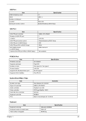
One type II CardBus PC Card slot One SmartBus slot Upgradeable memory Removable drives EasyPort port replicator Keyboard and Pointing Device ! 84-/85-key Windows keyboard ! Ergonomically-centered touchpad pointing device with scroll function I/O Ports One type II CardBus PC Card slot(s) One RJ-45 jack for Ethernet One... RJ-11 phone jack One DC-in jack (AC adapter) One parallel port (ECP/EPP compliant) One external monitor port One PS/2 keyboard/mouse port One audio line-out jack One microphone-in jack Two USB ports One port replicator connector One firewire 1394 port One S-video output...
One type II CardBus PC Card slot One SmartBus slot Upgradeable memory Removable drives EasyPort port replicator Keyboard and Pointing Device ! 84-/85-key Windows keyboard ! Ergonomically-centered touchpad pointing device with scroll function I/O Ports One type II CardBus PC Card slot(s) One RJ-45 jack for Ethernet One... RJ-11 phone jack One DC-in jack (AC adapter) One parallel port (ECP/EPP compliant) One external monitor port One PS/2 keyboard/mouse port One audio line-out jack One microphone-in jack Two USB ports One port replicator connector One firewire 1394 port One S-video output...

TravelMate 620 Service Guide
Page 15
... devices (e.g., infrared printer, IR-aware computer). Interfaces with a desktop PC. Outputs sound 7 Touch-sensitive pointing device which functions like the left , center and right) Palmrest Keyboard Status indicators Infrared port Microphone Speaker Description Also called LCD (liquid-crystal display), diplays computer output. Inputs data into your computer. the center button serves...
... devices (e.g., infrared printer, IR-aware computer). Interfaces with a desktop PC. Outputs sound 7 Touch-sensitive pointing device which functions like the left , center and right) Palmrest Keyboard Status indicators Infrared port Microphone Speaker Description Also called LCD (liquid-crystal display), diplays computer output. Inputs data into your computer. the center button serves...

TravelMate 620 Service Guide
Page 21
... (complete with some applications. Chapter 1 13 When Scroll Lock is in uppercase. Scroll Lock does not work with the arithmetic operators +, -, *, and /). Lock Keys The keyboard has three lock keys which you need to connect an external keypad. Use this mode when you can toggle on , the screen moves one line...
... (complete with some applications. Chapter 1 13 When Scroll Lock is in uppercase. Scroll Lock does not work with the arithmetic operators +, -, *, and /). Lock Keys The keyboard has three lock keys which you need to connect an external keypad. Use this mode when you can toggle on , the screen moves one line...

TravelMate 620 Service Guide
Page 22
...on embedded keypad. Num Lock Off Hold Fn while using cursor-control keys. NOTE: If an external keyboard or keypad is indicated by small characters located on the keys. Main keyboard keys Hold Fn while typing letters on embedded keypad Hold j while using cursorcontrol keys. Type the ...letters in a normal keypad manner. To simplify the keyboard legend, cursor-control key symbols are not printed on the upper right corner of the keycaps. It is connected to the computer, ...
...on embedded keypad. Num Lock Off Hold Fn while using cursor-control keys. NOTE: If an external keyboard or keypad is indicated by small characters located on the keys. Main keyboard keys Hold Fn while typing letters on embedded keypad Hold j while using cursorcontrol keys. Type the ...letters in a normal keypad manner. To simplify the keyboard legend, cursor-control key symbols are not printed on the upper right corner of the keycaps. It is connected to the computer, ...

TravelMate 620 Service Guide
Page 23
Windows Keys The keyboard has two keys that perform Windows-specific functions. Combinations with this key perform shortcut functions. Below are a few examples: + Tab (Activates next taskbar button) + E (Explores My Computer) + F (Finds Document) + M (Minimizes All) Shift + + M (Undoes Minimize All) + R (Displays the Run...dialog box) Opens a context menu (same as a right-click). Chapter 1 15 Key Windows logo key Application key Icon Description Start button.
Windows Keys The keyboard has two keys that perform Windows-specific functions. Combinations with this key perform shortcut functions. Below are a few examples: + Tab (Activates next taskbar button) + E (Explores My Computer) + F (Finds Document) + M (Minimizes All) Shift + + M (Undoes Minimize All) + R (Displays the Run...dialog box) Opens a context menu (same as a right-click). Chapter 1 15 Key Windows logo key Application key Icon Description Start button.

TravelMate 620 Service Guide
Page 26
They are called launch keys. The mail button is used to launch your system. The web browser button, by default is used to launch a multimedia application that came bundled with your internet browser. 18 Chapter 1 These buttons are designated as P1, P2, P3, Mail button and Web browser button. By default, buttons P1and P2 are five buttons. The LED of the keyboard are users programmable. Launch Keys Located at the top of the mail button will flash when the user has received an incoming email. The P3, by default is used to launch the mail application.
They are called launch keys. The mail button is used to launch your system. The web browser button, by default is used to launch a multimedia application that came bundled with your internet browser. 18 Chapter 1 These buttons are designated as P1, P2, P3, Mail button and Web browser button. By default, buttons P1and P2 are five buttons. The LED of the keyboard are users programmable. Launch Keys Located at the top of the mail button will flash when the user has received an incoming email. The P3, by default is used to launch the mail application.
TravelMate 620 Service Guide
Page 28
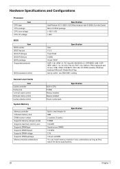
... package Memory module combinations Specification Intel Pentium III 1/1.066/1.133 GHz processor with 512KB L2 on-die Cache Micro-FCPGA package 1.40V/1.15V 1.25V Specification Acer V 3.3 Flash ROM 512KB 32-pin TSOP ACPI 1.0b, APM 1.2, PC Card 95, SM BIOS 2.3, EPP/IEEE 1284, ECP/ IEEE 1284 1.7 & 1.9, IrDA, ...PCI 2.2, PnP 1.0a, DMI 2.0, PS/2 keyboard and mouse, USB, VESA VGA BIOS, DDC-2B, CD-ROM bootable, Windows keyboard Microsoft Simple Boot Flag Set by switch, see SW1(SW1) setting Built-in CPU 512KB Always enabled Always enabled...
... package Memory module combinations Specification Intel Pentium III 1/1.066/1.133 GHz processor with 512KB L2 on-die Cache Micro-FCPGA package 1.40V/1.15V 1.25V Specification Acer V 3.3 Flash ROM 512KB 32-pin TSOP ACPI 1.0b, APM 1.2, PC Card 95, SM BIOS 2.3, EPP/IEEE 1284, ECP/ IEEE 1284 1.7 & 1.9, IrDA, ...PCI 2.2, PnP 1.0a, DMI 2.0, PS/2 keyboard and mouse, USB, VESA VGA BIOS, DDC-2B, CD-ROM bootable, Windows keyboard Microsoft Simple Boot Flag Set by switch, see SW1(SW1) setting Built-in CPU 512KB Always enabled Always enabled...
TravelMate 620 Service Guide
Page 33
...Setup) IrDA FIR port IRQ (in BIOS Setup) ECP DMA channel (in BIOS Setup) Optional IrDA FIR port DRQ (in Intel Almador-M / ICH3-M Keyboard Item Keyboard controller Keyboard vendor & model name Total number of slots Access location Supports ZV (Zoomed Video) port Supports 32 bit CardBus O2 OZ6933 Type-III/II One... ZV support Yes (IRQ11) Specification System Board Major Chips Item System core logic Super I/O controller Audio controller Video controller Hard disk drive controller Keyboard controller RTC Controller Intel Almador-M / ICH3-M SMSC LPC47N267 Realtech ALC 200 ATI Rage Mobility -
...Setup) IrDA FIR port IRQ (in BIOS Setup) ECP DMA channel (in BIOS Setup) Optional IrDA FIR port DRQ (in Intel Almador-M / ICH3-M Keyboard Item Keyboard controller Keyboard vendor & model name Total number of slots Access location Supports ZV (Zoomed Video) port Supports 32 bit CardBus O2 OZ6933 Type-III/II One... ZV support Yes (IRQ11) Specification System Board Major Chips Item System core logic Super I/O controller Audio controller Video controller Hard disk drive controller Keyboard controller RTC Controller Intel Almador-M / ICH3-M SMSC LPC47N267 Realtech ALC 200 ATI Rage Mobility -

TravelMate 620 Service Guide
Page 34
...) Display technology Resolution Supports colors Optical Specification Brightness control Contrast control Specification Hitachi TX38D95VC1CAM 15 TFT SXGA+ (1400x1050) 262K keyboard hotkey No 26 Chapter 1 Keyboard Item Windows 95 keys Yes Internal & external keyboard work simultaneously Yes Specification Battery Item Vendor & model name Battery Type Pack capacity Cell voltage Number of LCD brightness. NOTE...
...) Display technology Resolution Supports colors Optical Specification Brightness control Contrast control Specification Hitachi TX38D95VC1CAM 15 TFT SXGA+ (1400x1050) 262K keyboard hotkey No 26 Chapter 1 Keyboard Item Windows 95 keys Yes Internal & external keyboard work simultaneously Yes Specification Battery Item Vendor & model name Battery Type Pack capacity Cell voltage Number of LCD brightness. NOTE...
TravelMate 620 Service Guide
Page 36
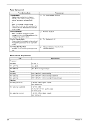
... in touchpad, and an external PS/2 pointing device are idle for power management are set to peak) 62.6~500Hz: 4G 28 Chapter 1 Display Standby Mode Keyboard, built-in standby mode. (spindle turned-off) Environmental Requirements Item Temperature Operating Non-operating Non-operating Humidity Operating Non-operating Non-operating Vibration Operating (unpacked...
... in touchpad, and an external PS/2 pointing device are idle for power management are set to peak) 62.6~500Hz: 4G 28 Chapter 1 Display Standby Mode Keyboard, built-in standby mode. (spindle turned-off) Environmental Requirements Item Temperature Operating Non-operating Non-operating Humidity Operating Non-operating Non-operating Vibration Operating (unpacked...

TravelMate 620 Service Guide
Page 37
...port, 1 RJ-45 LAN port, 1 DC-in jack (AC adapter), 1 FIR port, 1 parallel port, 1 serial port, 1 external monitor port, 1 PS/2 keyboard/mouse port, 1 mini docking station connector, 2 USB ports, 1 speaker/headphone-out jack, 1 audio line-in jack, 1 microphone-in jack, 1 fingerprint recognition sensor...Size Function System BIOS UMB Area VGA BIOS Video memory (VRAM) Conventional memory Function DMA controller-1 Interrupt controller-1 Timer 1 Keyboard controller 38859 chip select System speaker out DMA controller-1 System speaker Real-time clock and NMI mask DMA page register Interrupt controller...
...port, 1 RJ-45 LAN port, 1 DC-in jack (AC adapter), 1 FIR port, 1 parallel port, 1 serial port, 1 external monitor port, 1 PS/2 keyboard/mouse port, 1 mini docking station connector, 2 USB ports, 1 speaker/headphone-out jack, 1 audio line-in jack, 1 microphone-in jack, 1 fingerprint recognition sensor...Size Function System BIOS UMB Area VGA BIOS Video memory (VRAM) Conventional memory Function DMA controller-1 Interrupt controller-1 Timer 1 Keyboard controller 38859 chip select System speaker out DMA controller-1 System speaker Real-time clock and NMI mask DMA page register Interrupt controller...

TravelMate 620 Service Guide
Page 50
PQA Vx_x xx-xx-xx Diag Result Diag MANUALTTeEstSITtems AUTO[ ] SyTstEeSmTBoard [ ] Memory [ ] Keyboard [ ] Video [ ] Parallel Port [ ] Serial Port [ ] Diskette Drive [ ] Hard Disk [ ] CD-ROM [ ] Coprocessor [ ] Pointing Dev. [ ] Cache SysInfo Option Exit SPACE: mark/unmark selecting item ESC : return ...
PQA Vx_x xx-xx-xx Diag Result Diag MANUALTTeEstSITtems AUTO[ ] SyTstEeSmTBoard [ ] Memory [ ] Keyboard [ ] Video [ ] Parallel Port [ ] Serial Port [ ] Diskette Drive [ ] Hard Disk [ ] CD-ROM [ ] Coprocessor [ ] Pointing Dev. [ ] Cache SysInfo Option Exit SPACE: mark/unmark selecting item ESC : return ...

TravelMate 620 Service Guide
Page 53
For example, if you must first remove the keyboard, then disassemble the inside assembly frame in that need to remove the system board, you want to be removed during servicing. Start Battery A x 2 DIMM Cover CD/DVD ROM Module B x 2 HDD Cover Main Unit (see next page for details) Modem Board DIMM HDD Module CD/DVD ROM Drive HDD Bracket CD/DVD ROM FPC Cable HDD Chapter 3 45 Disassembly Procedure Flowchart The flowchart on the succeeding page gives you a graphic representation on the entire disassembly sequence and instructs you on the components that order.
For example, if you must first remove the keyboard, then disassemble the inside assembly frame in that need to remove the system board, you want to be removed during servicing. Start Battery A x 2 DIMM Cover CD/DVD ROM Module B x 2 HDD Cover Main Unit (see next page for details) Modem Board DIMM HDD Module CD/DVD ROM Drive HDD Bracket CD/DVD ROM FPC Cable HDD Chapter 3 45 Disassembly Procedure Flowchart The flowchart on the succeeding page gives you a graphic representation on the entire disassembly sequence and instructs you on the components that order.

TravelMate 620 Service Guide
Page 54
C x 2 Main Unit C x 2 RTC battery Upper Case Touchpad Frame Touchpad Keyboard Heatsink Plate CPU Screw x 4 CPU Fansink C x 6 CPU C x 1 Lower Case A x 2 Speakers Middle Cover C x 6 LCD Module E x 4 LCD Bezel D x 4 LCD F x 2 Inverter Board G x 6 LCD Bracket A x 2 Daughter Board Main Board A x 2 Screw List Item A B C D E F G Description Screw M2 X L4 (Black) Screw M2.5 X L6 (Black) Screw M2.5 X L8 ((Black) Screw M2.5 X L3.5 (Black) Screw M2 X L5 (Black) Screw M2.5 X L10 (Black) Screw M2 X L3 (Silver) 46 PCMCIA Socket Modem Cable Chapter 3
C x 2 Main Unit C x 2 RTC battery Upper Case Touchpad Frame Touchpad Keyboard Heatsink Plate CPU Screw x 4 CPU Fansink C x 6 CPU C x 1 Lower Case A x 2 Speakers Middle Cover C x 6 LCD Module E x 4 LCD Bezel D x 4 LCD F x 2 Inverter Board G x 6 LCD Bracket A x 2 Daughter Board Main Board A x 2 Screw List Item A B C D E F G Description Screw M2 X L4 (Black) Screw M2.5 X L6 (Black) Screw M2.5 X L8 ((Black) Screw M2.5 X L3.5 (Black) Screw M2 X L5 (Black) Screw M2.5 X L10 (Black) Screw M2 X L3 (Silver) 46 PCMCIA Socket Modem Cable Chapter 3

TravelMate 620 Service Guide
Page 60
Pry up and put it from both sides, then remove it on page 52 2. Remove the 2 screws from the main board. 52 Chapter 3 Lift the keyboard up the middle cover from the main unit. Disconnect the keyboard cable from the rear of the unit. 2. See "Removing the Middle Cover" on the upper case. 4. Disassembling the Main Unit Removing the Middle Cover 1. Removing the Keyboard 1. First, release the 2 screws on the rear of the unit as shown, then poke the 3 guide pins downward to release the keyboard. 3.
Pry up and put it from both sides, then remove it on page 52 2. Remove the 2 screws from the main board. 52 Chapter 3 Lift the keyboard up the middle cover from the main unit. Disconnect the keyboard cable from the rear of the unit. 2. See "Removing the Middle Cover" on the upper case. 4. Disassembling the Main Unit Removing the Middle Cover 1. Removing the Keyboard 1. First, release the 2 screws on the rear of the unit as shown, then poke the 3 guide pins downward to release the keyboard. 3.

TravelMate 620 Service Guide
Page 61
Removing the LCD Module 1. See "Removing the Middle Cover" on page 52 3. Disconnect the LED/inverter cable and the LCD coaxial cable from the main board. 5. Lift up the LCD module carefully. See "Removing the Keyboard" on page 52 2. Remove the keyboard. Remove the two screws as shown. 6. Chapter 3 53 Release the two screws on the main unit and the 4 screws as shown. 4. 5.
Removing the LCD Module 1. See "Removing the Middle Cover" on page 52 3. Disconnect the LED/inverter cable and the LCD coaxial cable from the main board. 5. Lift up the LCD module carefully. See "Removing the Keyboard" on page 52 2. Remove the keyboard. Remove the two screws as shown. 6. Chapter 3 53 Release the two screws on the main unit and the 4 screws as shown. 4. 5.

TravelMate 620 Service Guide
Page 62
See "Removing the Keyboard" on page 52 2. Disconnect the cable from the upper case. 3. Slide the heat sink plate this way, and remove the heat sink plate. 4. Remove the touchpad button and the scroll key from the touchpad board. 4. Disconnect the CPU fan sink cable. 54 Chapter 3 Removing the TouchPad Module 1. Remove the touchpad board from the upper case carefully. 2. See "Removing the Middle Cover" on page 52 3. Release the 4 screws on the CPU fan sink. 5. Snap off the touchpad frame from the upper case. Removing the CPU 1.
See "Removing the Keyboard" on page 52 2. Disconnect the cable from the upper case. 3. Slide the heat sink plate this way, and remove the heat sink plate. 4. Remove the touchpad button and the scroll key from the touchpad board. 4. Disconnect the CPU fan sink cable. 54 Chapter 3 Removing the TouchPad Module 1. Remove the touchpad board from the upper case carefully. 2. See "Removing the Middle Cover" on page 52 3. Release the 4 screws on the CPU fan sink. 5. Snap off the touchpad frame from the upper case. Removing the CPU 1.

TravelMate 620 Service Guide
Page 63
Removing the RTC 1. Chapter 3 55 Remove the CPU fan sink. 7. See "Removing the Keyboard" on page 52 2. Loose up the CPU secure knot. 8. See "Removing the Middle Cover" on page 52 3. 6. Disconnect the RTC connector from the mainboard. Remove the CPU.
Removing the RTC 1. Chapter 3 55 Remove the CPU fan sink. 7. See "Removing the Keyboard" on page 52 2. Loose up the CPU secure knot. 8. See "Removing the Middle Cover" on page 52 3. 6. Disconnect the RTC connector from the mainboard. Remove the CPU.


