
Travelmate 2300 User's Guide
Page 85
... drive's classification label (shown below) is 15 feet (4.6 meters). 15 Always disconnect all telephone lines from the wall outlet before serving or disassembling this unit. EVITTER TOUTE EXPOSITION AUX RAYONS. f If the product exhibits a distinct change in performance, indicating a need for this equipment. 16...type SPT-2, rated 7A 125V minimum, VDE approved or its equivalent. Keep them in your accessories box) for service. 12 The TravelMate series uses the lithium battery. English English 77 d If the product does not operate normally when the operating instructions are covered by...
... drive's classification label (shown below) is 15 feet (4.6 meters). 15 Always disconnect all telephone lines from the wall outlet before serving or disassembling this unit. EVITTER TOUTE EXPOSITION AUX RAYONS. f If the product exhibits a distinct change in performance, indicating a need for this equipment. 16...type SPT-2, rated 7A 125V minimum, VDE approved or its equivalent. Keep them in your accessories box) for service. 12 The TravelMate series uses the lithium battery. English English 77 d If the product does not operate normally when the operating instructions are covered by...

Travelmate 2300 User's Guide
Page 86
...;LEN ADVARSEL: LASERSTRÅLING NAR DEKSEL ÅPNESSTIRR IKKE INN I STRÅLEN LCD pixel statement The LCD unit is prohibited. Reverse engineering or disassembly is produced with wireless LAN and/or Bluetooth® only. Radio Device Regulatory Notice Note: Below regulatory information is for limited viewing uses only. EVITE...
...;LEN ADVARSEL: LASERSTRÅLING NAR DEKSEL ÅPNESSTIRR IKKE INN I STRÅLEN LCD pixel statement The LCD unit is prohibited. Reverse engineering or disassembly is produced with wireless LAN and/or Bluetooth® only. Radio Device Regulatory Notice Note: Below regulatory information is for limited viewing uses only. EVITE...
TravelMate 2300/4000/4500 Service Guide
Page 58
... computer, you remove the stripe cover, please be careful not to disassemble the notebook computer for the different components vary in size. Chapter 3 51 When you need the following tools: T Wrist grounding strap and ...screwdriver T Plastic flat head screw driver T Tweezers NOTE: The screws for maintenance and troubleshooting. Chapter 3 Machine Disassembly and Replacement This chapter contains step-by-step procedures on how to scrape the cover. During the disassembly process, group the screws with the corresponding components to avoid mismatch when putting back the components.
... computer, you remove the stripe cover, please be careful not to disassemble the notebook computer for the different components vary in size. Chapter 3 51 When you need the following tools: T Wrist grounding strap and ...screwdriver T Plastic flat head screw driver T Tweezers NOTE: The screws for maintenance and troubleshooting. Chapter 3 Machine Disassembly and Replacement This chapter contains step-by-step procedures on how to scrape the cover. During the disassembly process, group the screws with the corresponding components to avoid mismatch when putting back the components.

TravelMate 2300/4000/4500 Service Guide
Page 59
...: 1. Mini PCI cover here also called RAM/Wireless cover. Unplug the AC adapter and all peripherals. 2. Please group same type of screw together as you disassemble the system for your reference. Please pay attention to worry about mix them up. However, please notice that you do the following locations together. There...to the system and all power and signal cables from the system. 3. Remove the battery pack. General Information Before You Begin Before proceeding with the disassembly procedure, make sure that you have to remove the HDD, the heatsink cover to see these screws.
...: 1. Mini PCI cover here also called RAM/Wireless cover. Unplug the AC adapter and all peripherals. 2. Please group same type of screw together as you disassemble the system for your reference. Please pay attention to worry about mix them up. However, please notice that you do the following locations together. There...to the system and all power and signal cables from the system. 3. Remove the battery pack. General Information Before You Begin Before proceeding with the disassembly procedure, make sure that you have to remove the HDD, the heatsink cover to see these screws.
TravelMate 2300/4000/4500 Service Guide
Page 61
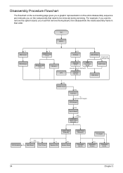
... need to be removed during servicing. For example, if you want to remove the system board, you on the entire disassembly sequence and instructs you must first remove the keyboard, then disassemble the inside assembly frame in -1 Cover *4 Speaker Set B*2 Modem Board Upper Case Assembly Touchpad Touchpad Bracket B*2 Bluetooth Module Touchpad Board...
... need to be removed during servicing. For example, if you want to remove the system board, you on the entire disassembly sequence and instructs you must first remove the keyboard, then disassemble the inside assembly frame in -1 Cover *4 Speaker Set B*2 Modem Board Upper Case Assembly Touchpad Touchpad Bracket B*2 Bluetooth Module Touchpad Board...

TravelMate 2300/4000/4500 Service Guide
Page 68
... to main board FFC. 3. Disconnect the bluetooth cable. 5. Chapter 3 61 Disconnect the touchpad FFC from the touchpad board. Disassembling the Upper Case Assembly 1. Disconnect the touchpad board to the lower case assembly. 8. Disassembling the Main Unit Separate the Main Unit Into the Upper and the Lower Case Assembly 1. Then detach the touchpad...
... to main board FFC. 3. Disconnect the bluetooth cable. 5. Chapter 3 61 Disconnect the touchpad FFC from the touchpad board. Disassembling the Upper Case Assembly 1. Disconnect the touchpad board to the lower case assembly. 8. Disassembling the Main Unit Separate the Main Unit Into the Upper and the Lower Case Assembly 1. Then detach the touchpad...

TravelMate 2300/4000/4500 Service Guide
Page 69
Disconnect the touchpad board to touchpad FFC from the upper case. 6. Remove the touchpad board to touchpad FFC. 7. 4. Remove the touchpad board from the uppwer case assembly. 8. Detach the touchpad bracket from the upper case. 11. Disconnect the bluetooth module then remove it. Remove the four screws holding the touchpad bracket. 9. Remove the touchpad from the upper case assembly. 10. Remove the three screws that secure the bluetooth module. 12. Disassembling the Lower Case Assembly 62 Chapter 3 Remove the two screws that secure the touchpad board. 5.
Disconnect the touchpad board to touchpad FFC from the upper case. 6. Remove the touchpad board to touchpad FFC. 7. 4. Remove the touchpad board from the uppwer case assembly. 8. Detach the touchpad bracket from the upper case. 11. Disconnect the bluetooth module then remove it. Remove the four screws holding the touchpad bracket. 9. Remove the touchpad from the upper case assembly. 10. Remove the three screws that secure the bluetooth module. 12. Disassembling the Lower Case Assembly 62 Chapter 3 Remove the two screws that secure the touchpad board. 5.

TravelMate 2300/4000/4500 Service Guide
Page 72
Remove the four screw caps as shown. 2. Then remove the right bracket. 12. Disassembling the LCD Module 1. Then detach the LCD bezel from the LCD cover carefully. . 10. Disconnect the inverter board then remove it. 5. Remove another screw holding ...
Remove the four screw caps as shown. 2. Then remove the right bracket. 12. Disassembling the LCD Module 1. Then detach the LCD bezel from the LCD cover carefully. . 10. Disconnect the inverter board then remove it. 5. Remove another screw holding ...

TravelMate 2300/4000/4500 Service Guide
Page 74
Disassembling the Optical Drive Module 1. Chapter 3 67 Push the ODD holder as the picture shows. 2. Disconnect the ODD connector board then remove it. Then take the hard disc drive out from the HDD bracket. Remove the two screws holding the HDD bracket on one side. 2. Remove the two screws that secure the optical disc drive and the ODD holder. 3. Disassembling the External Modules Disassembling the HDD Module 1. Detach the ODD holder. 5. Remove the four screws as shown. 4. Remove another two screws holding the HDD bracket on the other side. 3.
Disassembling the Optical Drive Module 1. Chapter 3 67 Push the ODD holder as the picture shows. 2. Disconnect the ODD connector board then remove it. Then take the hard disc drive out from the HDD bracket. Remove the two screws holding the HDD bracket on one side. 2. Remove the two screws that secure the optical disc drive and the ODD holder. 3. Disassembling the External Modules Disassembling the HDD Module 1. Detach the ODD holder. 5. Remove the four screws as shown. 4. Remove another two screws holding the HDD bracket on the other side. 3.

TravelMate 2300/4000/4500 Service Guide
Page 76
Chapter 4 Troubleshooting Use the following procedure as possible. 2. Distinguish symptom. Disassemble and assemble the unit without any problem occurs, you can perform visual inspection before you fellow this model. there are no obvious shorts or opens; ... the customer-reported symptoms and go on or stay on page 85 Chapter 4 69 No beep or error codes are properly connected and secured; Non-Acer products, prototype cards, or modified options can check the following table with the verified symptom to determine which page to go to re-create the...
Chapter 4 Troubleshooting Use the following procedure as possible. 2. Distinguish symptom. Disassemble and assemble the unit without any problem occurs, you can perform visual inspection before you fellow this model. there are no obvious shorts or opens; ... the customer-reported symptoms and go on or stay on page 85 Chapter 4 69 No beep or error codes are properly connected and secured; Non-Acer products, prototype cards, or modified options can check the following table with the verified symptom to determine which page to go to re-create the...


