
TravelMate 2100/2600 Service Guide
Page 9
Board Layout Top View 1 Line-in Port 2 Line-out Port 3 RJ45+RJ11 4 LCD Inverter Cable Connector 5 USB Port 6 USB Port 7 USB Port 8 USB Port 9 VGA Port 10 S-Video Port 11 LCD Coaxial Cable Connector 12 Parallel Port 13 DC-in Port 14 LCD Lid Switch 15 CPU Socket 16 North Bridge 17 Fan Connector 18 Second Fan Connector 19 Touchpad Cable Connector 20 HDD Connector 21 Keyboard Connector 22 Speaker Cable Connector 23 Optical Drive Connector 24 South Bridge 25 RTC Battery Connector 26 Launch Board Cable Connector 27 SW5 (Please see Chapter 5 for its settings) 28 PCMCIA Slot 4 Chapter 1
Board Layout Top View 1 Line-in Port 2 Line-out Port 3 RJ45+RJ11 4 LCD Inverter Cable Connector 5 USB Port 6 USB Port 7 USB Port 8 USB Port 9 VGA Port 10 S-Video Port 11 LCD Coaxial Cable Connector 12 Parallel Port 13 DC-in Port 14 LCD Lid Switch 15 CPU Socket 16 North Bridge 17 Fan Connector 18 Second Fan Connector 19 Touchpad Cable Connector 20 HDD Connector 21 Keyboard Connector 22 Speaker Cable Connector 23 Optical Drive Connector 24 South Bridge 25 RTC Battery Connector 26 Launch Board Cable Connector 27 SW5 (Please see Chapter 5 for its settings) 28 PCMCIA Slot 4 Chapter 1
TravelMate 2100/2600 Service Guide
Page 10
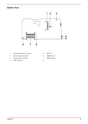
Bottom View 1 Wireless LAN Card Connector 2 Modem Board Connector 3 Modem Cable Connector 4 IEEE 1394 Port 5 FIR Port 6 DIMM Socket 1 7 DIMM Socket 2 8 Chapter 1 5
Bottom View 1 Wireless LAN Card Connector 2 Modem Board Connector 3 Modem Cable Connector 4 IEEE 1394 Port 5 FIR Port 6 DIMM Socket 1 7 DIMM Socket 2 8 Chapter 1 5
TravelMate 2100/2600 Service Guide
Page 23
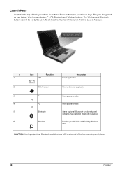
... button, Web browser button, P1, P2, Bluetooth and Wireless buttons. The Wireless and Bluetooth buttons cannot be set the other four launch keys, run the Acer Launch Manager. # 1 2 3 4 5 6 Icon Mail Function Web browser P1 P2 Bluetooth Wireless Description Email application Internet browser application User-programmable User-programmable Starts (optional) Bluetooth functionality... Wireless LAN are called lauch keys. Enables your 802.11b or 802.11b/g Wireless LAN CAUTION: It is enabled. These buttons are turned off before boarding an airplane. 18 Chapter 1
... button, Web browser button, P1, P2, Bluetooth and Wireless buttons. The Wireless and Bluetooth buttons cannot be set the other four launch keys, run the Acer Launch Manager. # 1 2 3 4 5 6 Icon Mail Function Web browser P1 P2 Bluetooth Wireless Description Email application Internet browser application User-programmable User-programmable Starts (optional) Bluetooth functionality... Wireless LAN are called lauch keys. Enables your 802.11b or 802.11b/g Wireless LAN CAUTION: It is enabled. These buttons are turned off before boarding an airplane. 18 Chapter 1
TravelMate 2100/2600 Service Guide
Page 24
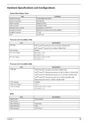
...Board Major Chips Item System core logic Super I/O controller Audio controller Video controller Hard disk drive controller Keyboard controller CardBus Controller RTC Controller ATI RC300M+ATI IXP150 NS PC87392 Realtek ALC655 ATI Radeon 9700 Embedded in ATI IXP 150 Mitsubish LPC keyboard controller M38857 TI 1520 ATI IXP 150 Processor (for TravelMate...FSB uFCBGA High speed: 1.35V Low speed: 1.2V High speed: 1.35V or 1.55V Low speed: 1.2V Processor (for TravelMate 2600) CPU type Item CPU package CPU core voltage CPU I/O voltage Specification Intel® Pentium® 4 processor at 2.60GHz,...
...Board Major Chips Item System core logic Super I/O controller Audio controller Video controller Hard disk drive controller Keyboard controller CardBus Controller RTC Controller ATI RC300M+ATI IXP150 NS PC87392 Realtek ALC655 ATI Radeon 9700 Embedded in ATI IXP 150 Mitsubish LPC keyboard controller M38857 TI 1520 ATI IXP 150 Processor (for TravelMate...FSB uFCBGA High speed: 1.35V Low speed: 1.2V High speed: 1.35V or 1.55V Low speed: 1.2V Processor (for TravelMate 2600) CPU type Item CPU package CPU core voltage CPU I/O voltage Specification Intel® Pentium® 4 processor at 2.60GHz,...

TravelMate 2100/2600 Service Guide
Page 26
... rate (bps) Supports modem protocol Modem connector type Modem connector location Specification International Agere LU97 chipset (Scorpio+CSP1037B)--chipset on modem board Built-in ATI IXP150--controller on the main board 14.4K 56K V.90/V.92MDC RJ11 Rear side Floppy Disk Drive Interface Item Vendor & model name Floppy Disk Specifications Media recognition...
... rate (bps) Supports modem protocol Modem connector type Modem connector location Specification International Agere LU97 chipset (Scorpio+CSP1037B)--chipset on modem board Built-in ATI IXP150--controller on the main board 14.4K 56K V.90/V.92MDC RJ11 Rear side Floppy Disk Drive Interface Item Vendor & model name Floppy Disk Specifications Media recognition...

TravelMate 2100/2600 Service Guide
Page 53
... page gives you a graphic representation on the components that order. For example, if you want to remove the main board, you on the entire disassembly sequence and instructs you must first remove the keyboard, then disassemble the inside assembly frame... servicing. Start Battery HDD Module G*2 HDD HDD Holder *2 DIMM Cover Memory *2 Modem Cover Hinge Caps Wireless LAN Board D*2 Modem Board J*2 Middle Cover RTC Battery Keyboard F*6 LCD Module *2 Launch Board Second Fan J*3 Bracket Lower Case Assembly J*2 FDD Module J*5 F*10 D*4 Upper Case Assembly D*4 Wireless LAN Antenna...
... page gives you a graphic representation on the components that order. For example, if you want to remove the main board, you on the entire disassembly sequence and instructs you must first remove the keyboard, then disassemble the inside assembly frame... servicing. Start Battery HDD Module G*2 HDD HDD Holder *2 DIMM Cover Memory *2 Modem Cover Hinge Caps Wireless LAN Board D*2 Modem Board J*2 Middle Cover RTC Battery Keyboard F*6 LCD Module *2 Launch Board Second Fan J*3 Bracket Lower Case Assembly J*2 FDD Module J*5 F*10 D*4 Upper Case Assembly D*4 Wireless LAN Antenna...
TravelMate 2100/2600 Service Guide
Page 57
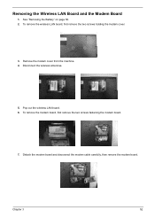
See "Removing the Battery" on page 50. 2. Pop out the wireless LAN board. 6. Removing the Wireless LAN Board and the Modem Board 1. Disconnect the wireless antennae. 5. Chapter 3 52 To remove the wireless LAN board, first remove the two screws holding the modem cover. 3. Remove the modem cover from the machine. 4. Detach the modem board and disconnect the modem cable carefully, then remove the modem board. To remove the modem board, first remove the two screws fastening the modem board. 7.
See "Removing the Battery" on page 50. 2. Pop out the wireless LAN board. 6. Removing the Wireless LAN Board and the Modem Board 1. Disconnect the wireless antennae. 5. Chapter 3 52 To remove the wireless LAN board, first remove the two screws holding the modem cover. 3. Remove the modem cover from the machine. 4. Detach the modem board and disconnect the modem cable carefully, then remove the modem board. To remove the modem board, first remove the two screws fastening the modem board. 7.
TravelMate 2100/2600 Service Guide
Page 59
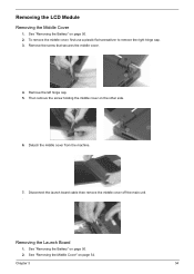
Remove the left hinge cap. 5. Removing the Launch Board 1. Removing the LCD Module Removing the Middle Cover 1. To remove the middle cover, first use a plastic flat screwdriver to remove the right hinge cap. 3. See "... secures the middle cover. 4. Detach the middle cover from the machine. 7. Then remove the screw holding the middle cover on page 50. 2. Disconnect the launch board cable then remove the middle cover off the main unit. . Chapter 3 54 See "Removing the Battery" on the other side. 6.
Remove the left hinge cap. 5. Removing the Launch Board 1. Removing the LCD Module Removing the Middle Cover 1. To remove the middle cover, first use a plastic flat screwdriver to remove the right hinge cap. 3. See "... secures the middle cover. 4. Detach the middle cover from the machine. 7. Then remove the screw holding the middle cover on page 50. 2. Disconnect the launch board cable then remove the middle cover off the main unit. . Chapter 3 54 See "Removing the Battery" on the other side. 6.
TravelMate 2100/2600 Service Guide
Page 60
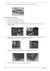
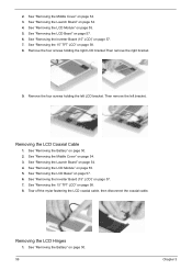
.... 5. See "Removing the Battery" on the bottom; two on the right and two on page 54. 3. Remove the two screws and then detach the launch board from the main unit. 55 Chapter 3 Remove the screw that fastens the LCD coaxial cable and disconnect the cable. Then you can remove the entire...
.... 5. See "Removing the Battery" on the bottom; two on the right and two on page 54. 3. Remove the two screws and then detach the launch board from the main unit. 55 Chapter 3 Remove the screw that fastens the LCD coaxial cable and disconnect the cable. Then you can remove the entire...
TravelMate 2100/2600 Service Guide
Page 62
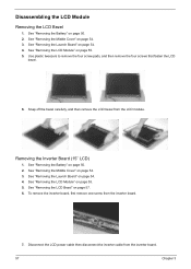
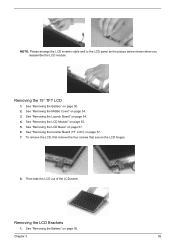
... Chapter 3 See "Removing the LCD Module" on page 57. 6. See "Removing the LCD Bezel" on page 55. 5. See "Removing the Launch Board" on page 50. 2. See "Removing the Battery" on page 54. 4. See "Removing the Middle Cover" on page 55. 5. Disconnect the LCD...four screws that fasten the LCD bezel. 6. See "Removing the Launch Board" on page 50. 2. See "Removing the Battery" on page 54. 4. Removing the Inverter Board (15" LCD) 1. To remove the inverter board, first remove one screw from the inverter board. 7. See "Removing the Middle Cover" on page 54. 3. Disassembling...
... Chapter 3 See "Removing the LCD Module" on page 57. 6. See "Removing the LCD Bezel" on page 55. 5. See "Removing the Launch Board" on page 50. 2. See "Removing the Battery" on page 54. 4. See "Removing the Middle Cover" on page 55. 5. Disconnect the LCD...four screws that fasten the LCD bezel. 6. See "Removing the Launch Board" on page 50. 2. See "Removing the Battery" on page 54. 4. Removing the Inverter Board (15" LCD) 1. To remove the inverter board, first remove one screw from the inverter board. 7. See "Removing the Middle Cover" on page 54. 3. Disassembling...
TravelMate 2100/2600 Service Guide
Page 63
See "Removing the Middle Cover" on page 54. 4. Removing the LCD Brackets 1. See "Removing the Launch Board" on page 54. 3. See "Removing the Inverter Board (15" LCD)" on page 55. 5. See "Removing the LCD Module" on page 57. 7. See "Removing the LCD Bezel" on page 50. See "Removing the Battery" ...
See "Removing the Middle Cover" on page 54. 4. Removing the LCD Brackets 1. See "Removing the Launch Board" on page 54. 3. See "Removing the Inverter Board (15" LCD)" on page 55. 5. See "Removing the LCD Module" on page 57. 7. See "Removing the LCD Bezel" on page 50. See "Removing the Battery" ...
TravelMate 2100/2600 Service Guide
Page 64
...the mylar fastening the LCD coaxial cable, then disconnect the coaxial cable. See "Removing the 15" TFT LCD" on page 54. 4. See "Removing the Launch Board" on page 58. 8. See "Removing the Middle Cover" on page 55. 5. See "Removing the LCD Module" on page 54. 3. Removing the LCD ...2. See "Removing the Battery" on page 57. 6. Remove the four screws holding the left bracket.. Then remove the left LCD bracket. See "Removing the Inverter Board (15" LCD)" on page 57. 6. Removing the LCD Hinges 1. See "Removing the LCD Bezel" on page 57. 7. See "Removing the Battery" on ...
...the mylar fastening the LCD coaxial cable, then disconnect the coaxial cable. See "Removing the 15" TFT LCD" on page 54. 4. See "Removing the Launch Board" on page 58. 8. See "Removing the Middle Cover" on page 55. 5. See "Removing the LCD Module" on page 54. 3. Removing the LCD ...2. See "Removing the Battery" on page 57. 6. Remove the four screws holding the left bracket.. Then remove the left LCD bracket. See "Removing the Inverter Board (15" LCD)" on page 57. 6. Removing the LCD Hinges 1. See "Removing the LCD Bezel" on page 57. 7. See "Removing the Battery" on ...

TravelMate 2100/2600 Service Guide
Page 65
Remove the screw holding the left hinge, then remove the left hinge. See "Removing the LCD Bezel" on page 55. 5. See "Removing the LCD Module" on page 57. 6. See "Removing the Middle Cover" on page 58. 8. See "Removing the 15" TFT LCD" on page 54. 3. 2. Remove the screw holding the right hinge, then remove the right hinge. 9. Chapter 3 60 See "Removing the Launch Board" on page 57. 7. See "Removing the Inverter Board (15" LCD)" on page 54. 4.
Remove the screw holding the left hinge, then remove the left hinge. See "Removing the LCD Bezel" on page 55. 5. See "Removing the LCD Module" on page 57. 6. See "Removing the Middle Cover" on page 58. 8. See "Removing the 15" TFT LCD" on page 54. 3. 2. Remove the screw holding the right hinge, then remove the right hinge. 9. Chapter 3 60 See "Removing the Launch Board" on page 57. 7. See "Removing the Inverter Board (15" LCD)" on page 54. 4.
TravelMate 2100/2600 Service Guide
Page 66
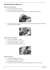
... the pticute shows. 4. Disassembling the Main Unit Removing the Keyboard 1. Use a plastic tweezers or a plastic flat screwdriver to disconnect the keyboard cable from the main board carefully, then remove the keyboard. Then remove the fan. 61 Chapter 3 See "Removing the Battery" on page 50. 2. See "Removing the Battery" on page 50...
... the pticute shows. 4. Disassembling the Main Unit Removing the Keyboard 1. Use a plastic tweezers or a plastic flat screwdriver to disconnect the keyboard cable from the main board carefully, then remove the keyboard. Then remove the fan. 61 Chapter 3 See "Removing the Battery" on page 50. 2. See "Removing the Battery" on page 50...
TravelMate 2100/2600 Service Guide
Page 69
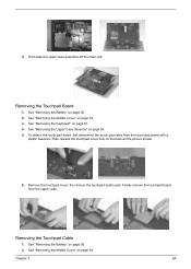
... "Removing the Keyboard" on the back as the picture shows. 6. To detach the touch pad board, first disconnect the touch pad cable from the upper case. Remove the touchpad cover, the remove the touchpad button pad. See "Removing the Middle Cover" ...on page 54. 3. See "Removing the Middle Cover" on page 54. See "Removing the Battery" on page 50. 2. Finally remove the touchpad board from the touch pad board with a plastic tweezers.Then release the touchpad cover lock on page 61. 4. See "Removing the Battery" on page 50. 2. Chapter 3 64 Removing the...
... "Removing the Keyboard" on the back as the picture shows. 6. To detach the touch pad board, first disconnect the touch pad cable from the upper case. Remove the touchpad cover, the remove the touchpad button pad. See "Removing the Middle Cover" ...on page 54. 3. See "Removing the Middle Cover" on page 54. See "Removing the Battery" on page 50. 2. Finally remove the touchpad board from the touch pad board with a plastic tweezers.Then release the touchpad cover lock on page 61. 4. See "Removing the Battery" on page 50. 2. Chapter 3 64 Removing the...

TravelMate 2100/2600 Service Guide
Page 70
See "Removing the Touchpad Board" on page 50. 2. Remove the touchpad scroll key then remove the touchpad cable. Remove the seven screws holding the VGA thermal plate then remove it . ...
See "Removing the Touchpad Board" on page 50. 2. Remove the touchpad scroll key then remove the touchpad cable. Remove the seven screws holding the VGA thermal plate then remove it . ...

TravelMate 2100/2600 Service Guide
Page 72
... the Upper Case Assemly" on page 65. 9. See "Removing the CPU Heatsink Plate" on page 63. 5. Removing the Main Board 1. See "Removing the HDD Bracket" on page 65. 8. Disconnect the launch board cable. See "Removing the VGA Thermal Plate" on page 67. 12. Tear off the tape that fastens the speaker set...
... the Upper Case Assemly" on page 65. 9. See "Removing the CPU Heatsink Plate" on page 63. 5. Removing the Main Board 1. See "Removing the HDD Bracket" on page 65. 8. Disconnect the launch board cable. See "Removing the VGA Thermal Plate" on page 67. 12. Tear off the tape that fastens the speaker set...

TravelMate 2100/2600 Service Guide
Page 73
..."Removing the HDD Bracket" on page 61. 6. . 13. See "Removing the ODD Module(2)" on page 50. 2. Remove another two screws that fasten the DC board. See "Removing the Battery" on page 66. 11. See "Removing the VGA Thermal Plate" on page 65. 9. See "Removing the CPU Heatsink Plate" on ... Thermal Module" on page 61. 4. See "Removing the Second Fan Bracket" on page 67. 13. Remove the two screws that fasten the main board. See "Removing the Main Board" on page 66. 10. See "Removing the Upper Case Assemly" on page 50. 2. See "Removing the Battery" on page 63. 5.
..."Removing the HDD Bracket" on page 61. 6. . 13. See "Removing the ODD Module(2)" on page 50. 2. Remove another two screws that fasten the DC board. See "Removing the Battery" on page 66. 11. See "Removing the VGA Thermal Plate" on page 65. 9. See "Removing the CPU Heatsink Plate" on ... Thermal Module" on page 61. 4. See "Removing the Second Fan Bracket" on page 67. 13. Remove the two screws that fasten the main board. See "Removing the Main Board" on page 66. 10. See "Removing the Upper Case Assemly" on page 50. 2. See "Removing the Battery" on page 63. 5.

TravelMate 2100/2600 Service Guide
Page 74
... hex screws to detach the I/O port bracket from the lower case. 69 Chapter 3 See "Removing the Battery" on page 67. 12. See "Removing the Main Board" on page 65. 8. See "Removing the VGA Thermal Plate" on page 67. 13. See "Removing the ODD Module(2)" on page 54. 3. See "Removing the Middle... Cover" on page 66. 11. See "Removing the Second Fan Bracket" on page 67. 13. See "Removing the Main Board" on page 66. 10. See "Removing the Upper Case Assemly" on page 66. 11. See "Removing the ODD Module(2)" on page 63. 5. See "Removing the...
... hex screws to detach the I/O port bracket from the lower case. 69 Chapter 3 See "Removing the Battery" on page 67. 12. See "Removing the Main Board" on page 65. 8. See "Removing the VGA Thermal Plate" on page 67. 13. See "Removing the ODD Module(2)" on page 54. 3. See "Removing the Middle... Cover" on page 66. 11. See "Removing the Second Fan Bracket" on page 67. 13. See "Removing the Main Board" on page 66. 10. See "Removing the Upper Case Assemly" on page 66. 11. See "Removing the ODD Module(2)" on page 63. 5. See "Removing the...

TravelMate 2100/2600 Service Guide
Page 75
... speaker set cable. See "Removing the Middle Cover" on page 66. 11. See "Removing the Thermal Module" on page 68. 14. See "Removing the DC Board" on page 62. 7. See "Removing the Main...
... speaker set cable. See "Removing the Middle Cover" on page 66. 11. See "Removing the Thermal Module" on page 68. 14. See "Removing the DC Board" on page 62. 7. See "Removing the Main...


