
Aspire 3640 / TravelMate 2440 Service Guide
Page 8
... Removing the Memory and the HDD Module 60 Removing the ODD Module 61 Removing the LCD Module 61 Disassembling the Main Unit 64 Separate the Main Unit Into the Upper and the... Lower Case Assembly 64 Disassembling the Lower Case Assembly 64 Disassembling the Upper Case Assembly 66 Disassembling the LCD Module 68 Disassembling the External Modules 70 Disassembling the HDD Module 70 Disassembling the ODD Module 70 Chpater 4 Troubleshooting ... 89 Top View 89 Bottom View 90 Chapter 6 FRU (Field Replaceable Unit) List 93 Aspire 3640/TravelMate 2440 Exploded Diagram 94 VIII
... Removing the Memory and the HDD Module 60 Removing the ODD Module 61 Removing the LCD Module 61 Disassembling the Main Unit 64 Separate the Main Unit Into the Upper and the... Lower Case Assembly 64 Disassembling the Lower Case Assembly 64 Disassembling the Upper Case Assembly 66 Disassembling the LCD Module 68 Disassembling the External Modules 70 Disassembling the HDD Module 70 Disassembling the ODD Module 70 Chpater 4 Troubleshooting ... 89 Top View 89 Bottom View 90 Chapter 6 FRU (Field Replaceable Unit) List 93 Aspire 3640/TravelMate 2440 Exploded Diagram 94 VIII

Aspire 3640 / TravelMate 2440 Service Guide
Page 9
...+ATI SB460 T Up to 2 GB of DDR2 533/677 MHz system memory, upgradeable to 2 GB using two soDIMM modules Display and graphics T 14.1" WXGA Acer CrystalBriteTM TFT LCD, 1280 x 800 pixel resolution, supporting simultaneous multi-window viewing via AcerAcer DridVistaTM T ATI Radeon® Xpress 200M chipset with integrated 3D graphics, featuring HyperMemory...
...+ATI SB460 T Up to 2 GB of DDR2 533/677 MHz system memory, upgradeable to 2 GB using two soDIMM modules Display and graphics T 14.1" WXGA Acer CrystalBriteTM TFT LCD, 1280 x 800 pixel resolution, supporting simultaneous multi-window viewing via AcerAcer DridVistaTM T ATI Radeon® Xpress 200M chipset with integrated 3D graphics, featuring HyperMemory...

Aspire 3640 / TravelMate 2440 Service Guide
Page 11
... GEN. Title BLOCK DIAGRAM Size Document Number Rev A3 Aspire 3640/TM2440 Date: Tuesday, February 14, 2006 Sheet 1 ooff 46 Chapter 1 3 Pad 34 KB 34 Acer Inc. 9F, 88, Sec.1, Hsin Tai Wu Rd., Hsichih, Taipei Hsien 221, Taiwan, R.O.C. ICS951413 (CV136 / CY28RS400) 3 Mobile CPU Yonah 478 4, 5 ... PCIE GPP I/F Ver.:A13, 71.RC410.D0U 6,7,8,9,10 SVIDEO/COMP LVDS RGB CRT PCIE x 1 PCIE x 1 New card 32 TVOUT 14 14"WXGA+ LCD 13 CRT 14 Mini Card*1 802.11A/B/G 27 PWR SW TPS223132 S S GND BOTTOM APL531230 3D3V_S5 1D5V_S0 43 APL5913 1D2V_S3 1D05V_S0 43 TPS51100 1D8V_S3 DDR_VREF_S0 43...
... GEN. Title BLOCK DIAGRAM Size Document Number Rev A3 Aspire 3640/TM2440 Date: Tuesday, February 14, 2006 Sheet 1 ooff 46 Chapter 1 3 Pad 34 KB 34 Acer Inc. 9F, 88, Sec.1, Hsin Tai Wu Rd., Hsichih, Taipei Hsien 221, Taiwan, R.O.C. ICS951413 (CV136 / CY28RS400) 3 Mobile CPU Yonah 478 4, 5 ... PCIE GPP I/F Ver.:A13, 71.RC410.D0U 6,7,8,9,10 SVIDEO/COMP LVDS RGB CRT PCIE x 1 PCIE x 1 New card 32 TVOUT 14 14"WXGA+ LCD 13 CRT 14 Mini Card*1 802.11A/B/G 27 PWR SW TPS223132 S S GND BOTTOM APL531230 3D3V_S5 1D5V_S0 43 APL5913 1D2V_S3 1D05V_S0 43 TPS51100 1D8V_S3 DDR_VREF_S0 43...

Aspire 3640 / TravelMate 2440 Service Guide
Page 12
Board Layout Top View 1 U39 2 U34 3 U29 4 U17 5 MIC1 6 LCD1 7 CVR1 LAN controller RTL8100CL 8 KB1 PCMCIA controller ENE CB1410 9 LED1 Clock generator ICS951413 10 TPAD1 KBC ENE3910 11 WLBTN1 Microphone cable connector 12 BTBTN1 LCD cable connector 13 SPKR1 LID switch 14 BT1 Keyboard FFC connector LED FFC connector Touch pad FFC connector Wireless LAN launch button Bluetooth launch button Speaker cable connector Bluetooth module cable connector 4 Chapter 1
Board Layout Top View 1 U39 2 U34 3 U29 4 U17 5 MIC1 6 LCD1 7 CVR1 LAN controller RTL8100CL 8 KB1 PCMCIA controller ENE CB1410 9 LED1 Clock generator ICS951413 10 TPAD1 KBC ENE3910 11 WLBTN1 Microphone cable connector 12 BTBTN1 LCD cable connector 13 SPKR1 LID switch 14 BT1 Keyboard FFC connector LED FFC connector Touch pad FFC connector Wireless LAN launch button Bluetooth launch button Speaker cable connector Bluetooth module cable connector 4 Chapter 1

Aspire 3640 / TravelMate 2440 Service Guide
Page 16
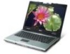
TravelMate 2440 front view # Icon Item Description 1 Display screen Also called LCD (liquid-crystal display), displays computer output. 2 Status indicators Light-Emitting Diodes (LEDs) that light up to show the status of the computer's functions and components. 3 ...
TravelMate 2440 front view # Icon Item Description 1 Display screen Also called LCD (liquid-crystal display), displays computer output. 2 Status indicators Light-Emitting Diodes (LEDs) that light up to show the status of the computer's functions and components. 3 ...

Aspire 3640 / TravelMate 2440 Service Guide
Page 19
6 Rear Panel Ethernet (RJ-45) Connects to an Ethernet 10/100/1000based network. # 1 Icon Item DC-in position. Connects to an AC adapter. Note: Do not cover or obstruct the opening of the fan. Chapter 1 11 Helps keep the computer cool. Powers the computer # Item 1 Battery lock 2 Cooling fan Description Locks the battery in jack External display (VGA) port Battery Bottom Panel Description Connects to a display device(e.g., external monitor, LCD projector).
6 Rear Panel Ethernet (RJ-45) Connects to an Ethernet 10/100/1000based network. # 1 Icon Item DC-in position. Connects to an AC adapter. Note: Do not cover or obstruct the opening of the fan. Chapter 1 11 Helps keep the computer cool. Powers the computer # Item 1 Battery lock 2 Cooling fan Description Locks the battery in jack External display (VGA) port Battery Bottom Panel Description Connects to a display device(e.g., external monitor, LCD projector).
Aspire 3640 / TravelMate 2440 Service Guide
Page 20
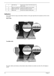
Aspire 3640: TravelMate 2420: The power, battery and wireless communication status indicators are visible even when the LCD display is closed. 12 Chapter 1 3 Hard disk bay Houses the computer's hard disk (secured with screws) 4 Memory compartment Houses the computer's main memory. 5 Battery release latch Release the battery for removal. 6 Battery bay Houses the computer's battery pack. Indicators The computer has four easy-to-read status indicators on the upper-right above the keyboard, and four on the front panel.
Aspire 3640: TravelMate 2420: The power, battery and wireless communication status indicators are visible even when the LCD display is closed. 12 Chapter 1 3 Hard disk bay Houses the computer's hard disk (secured with screws) 4 Memory compartment Houses the computer's main memory. 5 Battery release latch Release the battery for removal. 6 Battery bay Houses the computer's battery pack. Indicators The computer has four easy-to-read status indicators on the upper-right above the keyboard, and four on the front panel.

Aspire 3640 / TravelMate 2440 Service Guide
Page 29
.... Right-click on the Empowering Technology toolbard and select "Password Setup" to do so when running Acer eLock Management or Acer eRecovery Management for the first time. Acer ePower Management Acer ePower Management features a straightforward user interface. to save to external storage media. Name the newly created.... If you do not initialize the Empowering Technology password, you will appear in the profile list. You can adjust CPU speed, LCD brightness and other settings, or click on /off: Wireless LAN, Bluetooth, CardBus, FireWire (1394), Wired LAN and Optical Device ...
.... Right-click on the Empowering Technology toolbard and select "Password Setup" to do so when running Acer eLock Management or Acer eRecovery Management for the first time. Acer ePower Management Acer ePower Management features a straightforward user interface. to save to external storage media. Name the newly created.... If you do not initialize the Empowering Technology password, you will appear in the profile list. You can adjust CPU speed, LCD brightness and other settings, or click on /off: Wireless LAN, Bluetooth, CardBus, FireWire (1394), Wired LAN and Optical Device ...

Aspire 3640 / TravelMate 2440 Service Guide
Page 36
Item 1 Lens 2 Power indicator 28 Chapter 1 The Acer OrbiCam fully supports the Acer Video Conference technology so that you to know your Acer OrbiCam 1 23 # Item No. Getting to capture high-resolution photos or videos up front or at the back of the LCD panel. The camera's 225-degree ergonomic rotation allows you can transmit the best video quality over an instant Messenger service. Acer OrbiCam The Acer OrbiCam is a 1.3 megapixel CMOS camera appropriately mounted on the top of the LCD panel.
Item 1 Lens 2 Power indicator 28 Chapter 1 The Acer OrbiCam fully supports the Acer Video Conference technology so that you to know your Acer OrbiCam 1 23 # Item No. Getting to capture high-resolution photos or videos up front or at the back of the LCD panel. The camera's 225-degree ergonomic rotation allows you can transmit the best video quality over an instant Messenger service. Acer OrbiCam The Acer OrbiCam is a 1.3 megapixel CMOS camera appropriately mounted on the top of the LCD panel.

Aspire 3640 / TravelMate 2440 Service Guide
Page 37
... To change the capture resolution, click the displayed resolution at the back of the capture window, then select the desired resolution. Options Chapter 1 29 The Acer OrbiCam capture windows window appears. NOTE: Do not rotate the camera clockwise to prevent damage to achieve the desired angle. # Item No. Refer to the...: For your convenience, the camera snaps 45 degrees to match the position of your face in front or at the bottom right corner of the LCD panel. OR Click Start > All programs > Acer > Acer OrbiCam.
... To change the capture resolution, click the displayed resolution at the back of the capture window, then select the desired resolution. Options Chapter 1 29 The Acer OrbiCam capture windows window appears. NOTE: Do not rotate the camera clockwise to prevent damage to achieve the desired angle. # Item No. Refer to the...: For your convenience, the camera snaps 45 degrees to match the position of your face in front or at the bottom right corner of the LCD panel. OR Click Start > All programs > Acer > Acer OrbiCam.

Aspire 3640 / TravelMate 2440 Service Guide
Page 49
... system are turned off completely. Individual devices such as the CPU and hard disc may be power managed in this state. LCD 14.1" inch Item Typical Power Consumption (watt) Weight Physical Size(mm) Electrical Interface Support Color Viewing Angle (degree) Horizontal:... Right/Left Vertial: Upper/Lower Temperature Range( ° C) Operating Storage (shipping) LCD Inverter Item Vendor & model name Brightness conditions Input voltage (V) Input current (mA) Output voltage (V, rms) Output current (mA, rms) Output voltage ...
... system are turned off completely. Individual devices such as the CPU and hard disc may be power managed in this state. LCD 14.1" inch Item Typical Power Consumption (watt) Weight Physical Size(mm) Electrical Interface Support Color Viewing Angle (degree) Horizontal:... Right/Left Vertial: Upper/Lower Temperature Range( ° C) Operating Storage (shipping) LCD Inverter Item Vendor & model name Brightness conditions Input voltage (V) Input current (mA) Output voltage (V, rms) Output current (mA, rms) Output voltage ...

Aspire 3640 / TravelMate 2440 Service Guide
Page 55
... disable or auto. Format MM/DD/YYYY (month/day/ year) System Date This field reports the memory size of the extended memory in LCD only mode. Enabled: Customer Logo is displayed, and Summary Screen is disabled or enabled. Option: Enabled or Disabled Enables, disables Boot Menu ...Recovery function. Settings in CRT (or projector) only mode. Memory size is not allowed to factory defaults. Both: Simultaneously enable both the integrated LCD screen and the system's external video port (for an external CRT or projector). Option: Auto or Both Enables, disables the system boot from ...
... disable or auto. Format MM/DD/YYYY (month/day/ year) System Date This field reports the memory size of the extended memory in LCD only mode. Enabled: Customer Logo is displayed, and Summary Screen is disabled or enabled. Option: Enabled or Disabled Enables, disables Boot Menu ...Recovery function. Settings in CRT (or projector) only mode. Memory size is not allowed to factory defaults. Both: Simultaneously enable both the integrated LCD screen and the system's external video port (for an external CRT or projector). Option: Auto or Both Enables, disables the system boot from ...
Aspire 3640 / TravelMate 2440 Service Guide
Page 65
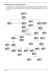
Start Battery Middle Cover H*2 DIMM Cover Memory P*1 Keyboard ODD Module E*1 J*2 on bottom side K*2 on top side LCD Module E*1 on upper case assemby E*12 on bottom side F*3 on bottom side A*2 on the components that order. For example, if you must first remove the ...
Start Battery Middle Cover H*2 DIMM Cover Memory P*1 Keyboard ODD Module E*1 J*2 on bottom side K*2 on top side LCD Module E*1 on upper case assemby E*12 on bottom side F*3 on bottom side A*2 on the components that order. For example, if you must first remove the ...
Aspire 3640 / TravelMate 2440 Service Guide
Page 68
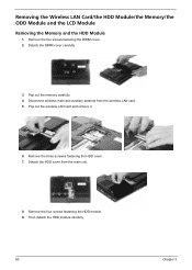
.... 9. Pop out the memory carefully. 4. Detach the DIMM cover carefully. 3. Removing the Wireless LAN Card/the HDD Module/the Memory/the ODD Module and the LCD Module Removing the Memory and the HDD Module 1. Remove the five screws fastening the DIMM cover. 2.
.... 9. Pop out the memory carefully. 4. Detach the DIMM cover carefully. 3. Removing the Wireless LAN Card/the HDD Module/the Memory/the ODD Module and the LCD Module Removing the Memory and the HDD Module 1. Remove the five screws fastening the DIMM cover. 2.
Aspire 3640 / TravelMate 2440 Service Guide
Page 69
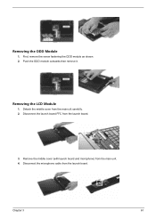
First, remove the screw fastening the ODD module as shown. 2. Removing the LCD Module 1. Remove the middle cover (with launch board and microphone) from the launch board. Disconnect the microphone cable from the main unit. 4. Push the ODD module outwards then remove it. Detach the middle cover from the launch board. 3. Disconnect the launch board FFC from the main uiit carefully. 2. Chapter 3 61 Removing the ODD Module 1.
First, remove the screw fastening the ODD module as shown. 2. Removing the LCD Module 1. Remove the middle cover (with launch board and microphone) from the launch board. Disconnect the microphone cable from the main unit. 4. Push the ODD module outwards then remove it. Detach the middle cover from the launch board. 3. Disconnect the launch board FFC from the main uiit carefully. 2. Chapter 3 61 Removing the ODD Module 1.
Aspire 3640 / TravelMate 2440 Service Guide
Page 70
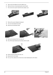
5. Remove the keyboard from the middle cover. . 8. Tear off the tapes fastening the wireless antenna cable. 13. Remove the two screws fastening the launch board. 7. Remove the screw holding the keyboard. 9. Then remove the launch board from the main unit. 12. Disconnect the LCD cable. 15. Disconnect the keyboard cable. 11. Take out the microphone from the main unit. 14. Turn over the notebook then remove two screws fastening the LCD module. 62 Chapter 3 Pull the antenna set from the middle cover. 6. Turn over the keyboard as shown. 10.
5. Remove the keyboard from the middle cover. . 8. Tear off the tapes fastening the wireless antenna cable. 13. Remove the two screws fastening the launch board. 7. Remove the screw holding the keyboard. 9. Then remove the launch board from the main unit. 12. Disconnect the LCD cable. 15. Disconnect the keyboard cable. 11. Take out the microphone from the main unit. 14. Turn over the notebook then remove two screws fastening the LCD module. 62 Chapter 3 Pull the antenna set from the middle cover. 6. Turn over the keyboard as shown. 10.

Aspire 3640 / TravelMate 2440 Service Guide
Page 71
Remove two screws fastening the LCD hinges. 17. Chapter 3 63 16. Then detach the LCD module from the main unit.
Remove two screws fastening the LCD hinges. 17. Chapter 3 63 16. Then detach the LCD module from the main unit.
Aspire 3640 / TravelMate 2440 Service Guide
Page 76
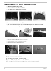
... the two screws fastening the LCD inverter. 5. Remove the two screws holding the LCD bezel. 3. Detach the CCD panel from the CCD bezel. 12. Then detach the LCD bezel from the CCD bezel. 11. Disconnect digital camera to LCD cable as shown. 2. Disassembling the LCD Module (with video camera) ...1. Take out the CCD from the LCD module. 4. Remove the four screw caps as shown. 9. Take out the LCD inverter from the LCD cover, then disconnect the LCD cable from the inverter. 6. NOTE...
... the two screws fastening the LCD inverter. 5. Remove the two screws holding the LCD bezel. 3. Detach the CCD panel from the CCD bezel. 12. Then detach the LCD bezel from the CCD bezel. 11. Disconnect digital camera to LCD cable as shown. 2. Disassembling the LCD Module (with video camera) ...1. Take out the CCD from the LCD module. 4. Remove the four screw caps as shown. 9. Take out the LCD inverter from the LCD cover, then disconnect the LCD cable from the inverter. 6. NOTE...

Aspire 3640 / TravelMate 2440 Service Guide
Page 77
.... 19. Remove the right bracket from the LCD panel. 14. Remove the four screws fastening the LCD left bracket from the LCD panel. 18. Chapter 3 69 Remove the four screws fastening the LCD right bracket. 20. Disconnect the LCD cable from the LCD. 16. Remove the two screws holding the ...wireless antenna set from the LCD. Remove the left bracket. 22. Tear off the tape fastening the LCD cable and detach the LCD cable from the LCD. 15. Take out...
.... 19. Remove the right bracket from the LCD panel. 14. Remove the four screws fastening the LCD left bracket from the LCD panel. 18. Chapter 3 69 Remove the four screws fastening the LCD right bracket. 20. Disconnect the LCD cable from the LCD. 16. Remove the two screws holding the ...wireless antenna set from the LCD. Remove the left bracket. 22. Tear off the tape fastening the LCD cable and detach the LCD cable from the LCD. 15. Take out...

Aspire 3640 / TravelMate 2440 Service Guide
Page 81
... to determine which page to go to. No beep or error codes are intended to test only Acer products. Other symptoms (i.e. Symptoms cannot be re-created (intermittent problems). Non-Acer products, prototype cards, or modified options can give false errors and invalid system responses. 1. Verify... Chapter 4 71 Obtain the failing symptoms in as much detail as a guide for computer problems. NOTE: The diagnostic tests are indicated. LCD display problems or others). Symptoms (Verified) Power failure. (The power indicator does not go to re-create the failure by running the ...
... to determine which page to go to. No beep or error codes are intended to test only Acer products. Other symptoms (i.e. Symptoms cannot be re-created (intermittent problems). Non-Acer products, prototype cards, or modified options can give false errors and invalid system responses. 1. Verify... Chapter 4 71 Obtain the failing symptoms in as much detail as a guide for computer problems. NOTE: The diagnostic tests are indicated. LCD display problems or others). Symptoms (Verified) Power failure. (The power indicator does not go to re-create the failure by running the ...


