Aspire 3630 / TravelMate 2430 Service Guide
Page 59
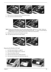
...Start from the main unit. See "Removing the Battery" on page 53. 3. Chapter 3 54 This can be secured well. 9. Then remove the wireless LAN card from 4, 3, 2 then 1. Then detch the CPU from the socket carefully. Then remove the CPU thermal module. When you average the ...you reassemble the CPU thermal module, secure the screws as the order: 1, 2, 3 then 4. Pop out the wireless LAN card. 4. See "Removing the Middle Cover" on page 50. 2. Removing the Wireless LAN Card 1. Disconnect the main and the auxiliary antennae. 5. 7. Release the CPU lock with a flat headed...
...Start from the main unit. See "Removing the Battery" on page 53. 3. Chapter 3 54 This can be secured well. 9. Then remove the wireless LAN card from 4, 3, 2 then 1. Then detch the CPU from the socket carefully. Then remove the CPU thermal module. When you average the ...you reassemble the CPU thermal module, secure the screws as the order: 1, 2, 3 then 4. Pop out the wireless LAN card. 4. See "Removing the Middle Cover" on page 50. 2. Removing the Wireless LAN Card 1. Disconnect the main and the auxiliary antennae. 5. 7. Release the CPU lock with a flat headed...
Aspire 3630 / TravelMate 2430 Service Guide
Page 60
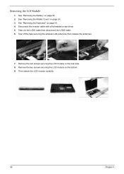
See "Removing the Middle Cover" on page 53. 4. See "Removing the Keyboard" on page 53. 3. Tear off the tape securing the wireless LAN antennae then release the antennae. 7. Take out the LVDS cable then disconnect the LVDS cable. 6. Then detach the LCD module carefully. 55 Chapter 3 Disconnect the inverter cable with a flat headed screw driver. 5. See "Removing the Battery" on the bottom. 9. Remove the two screws securing the LCD module on page 50. 2. Remove the two screws securing the LCD module on the rear side. 8. Removing the LCD Module 1.
See "Removing the Middle Cover" on page 53. 4. See "Removing the Keyboard" on page 53. 3. Tear off the tape securing the wireless LAN antennae then release the antennae. 7. Take out the LVDS cable then disconnect the LVDS cable. 6. Then detach the LCD module carefully. 55 Chapter 3 Disconnect the inverter cable with a flat headed screw driver. 5. See "Removing the Battery" on the bottom. 9. Remove the two screws securing the LCD module on page 50. 2. Remove the two screws securing the LCD module on the rear side. 8. Removing the LCD Module 1.


