TravelMate 240/250 Service Guide
Page 7
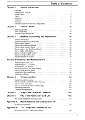
...Utilities 34 BIOS Setup Utility 34 BIOS Flash Utility 46 System Diagnostic Diskette 46 Chapter 3 Machine Disassembly and Replacement 48 General Information 49 Disassembly Procedure Flowchart 50 Removing the Battery 52 Removing the Memory Module 53 Removing the Modem Board 54... Problems 106 Undetermined Problems 107 Chapter 5 Jumper and Connector Locations 108 Chapter 6 FRU (Field Replaceable Unit) List 112 TravelMate 240/250 Exploded Diagram 113 Appendix A Model Definition and Configuration 126 Model Name Definition 126 Appendix B Test Compatible Components 128 ...
...Utilities 34 BIOS Setup Utility 34 BIOS Flash Utility 46 System Diagnostic Diskette 46 Chapter 3 Machine Disassembly and Replacement 48 General Information 49 Disassembly Procedure Flowchart 50 Removing the Battery 52 Removing the Memory Module 53 Removing the Modem Board 54... Problems 106 Undetermined Problems 107 Chapter 5 Jumper and Connector Locations 108 Chapter 6 FRU (Field Replaceable Unit) List 112 TravelMate 240/250 Exploded Diagram 113 Appendix A Model Definition and Configuration 126 Model Name Definition 126 Appendix B Test Compatible Components 128 ...
TravelMate 240/250 Service Guide
Page 57
... Replacement This chapter contains step-by-step procedures on how to avoid mismatch when putting back the components. Chapter 3 48 To disassemble the computer, you need the following tools: T Wrist grounding strap and conductive mat for preventing electrostatic discharge T Flat-bladed screw driver T Phillips screw driver T Tweezers T ...
... Replacement This chapter contains step-by-step procedures on how to avoid mismatch when putting back the components. Chapter 3 48 To disassemble the computer, you need the following tools: T Wrist grounding strap and conductive mat for preventing electrostatic discharge T Flat-bladed screw driver T Phillips screw driver T Tweezers T ...

TravelMate 240/250 Service Guide
Page 58
Turn off the power to the system and all power and signal cables from the system. 49 TravelMate 240/ 250 Unplug the AC adapter and all peripherals. 2. General Information Before You Begin Before proceeding with the disassembly procedure, make sure that you do the following: 1.
Turn off the power to the system and all power and signal cables from the system. 49 TravelMate 240/ 250 Unplug the AC adapter and all peripherals. 2. General Information Before You Begin Before proceeding with the disassembly procedure, make sure that you do the following: 1.
TravelMate 240/250 Service Guide
Page 59
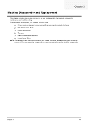
Disassembly Procedure Flowchart The flowchart on the succeeding page gives you a graphic representation on the components that order. Start Battery HDD Module *2 HDD HDD Holder *2 Dimm ... Board *4 PCMCIA Slot Touchpad Cable Upper Case *2 Speaker Set Chapter 3 50 For example, if you want to remove the main board, you on the entire disassembly sequence and instructs you must first remove the keyboard, then disassemble the inside assembly frame in that need to be removed during servicing.
Disassembly Procedure Flowchart The flowchart on the succeeding page gives you a graphic representation on the components that order. Start Battery HDD Module *2 HDD HDD Holder *2 Dimm ... Board *4 PCMCIA Slot Touchpad Cable Upper Case *2 Speaker Set Chapter 3 50 For example, if you want to remove the main board, you on the entire disassembly sequence and instructs you must first remove the keyboard, then disassemble the inside assembly frame in that need to be removed during servicing.

TravelMate 240/250 Service Guide
Page 64
Then take the hard disk drive out of the main unit. Remove the two screws that fasten the HDD holder. 4. See "Removing the Battery" on page 55. 3. Detach the hard disk drive from the HDD holder. 55 TravelMate 240/ 250 Disassembling the Hard Disk Drive Module 1. To remove the hard disk drive, pull the hard disk dirve carefully. 3. See "Removing the Hard Disk Drive Module" on page 52. 2. See "Removing the Battery" on page 52. 2. Removing the Hard Disk Drive Module 1.
Then take the hard disk drive out of the main unit. Remove the two screws that fasten the HDD holder. 4. See "Removing the Battery" on page 55. 3. Detach the hard disk drive from the HDD holder. 55 TravelMate 240/ 250 Disassembling the Hard Disk Drive Module 1. To remove the hard disk drive, pull the hard disk dirve carefully. 3. See "Removing the Hard Disk Drive Module" on page 52. 2. See "Removing the Battery" on page 52. 2. Removing the Hard Disk Drive Module 1.
TravelMate 240/250 Service Guide
Page 68
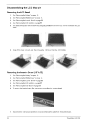
... cable then disconnect the inverter cable from the inverter board. 59 TravelMate 240/ 250 See "Removing the Middle Cover" on page 52. 2. Use plastic tweezers to remove the four screw pads, and then remove the four screws that fasten the LCD bezel. 6. Disassembling the LCD Module Removing the LCD Bezel 1. See "Removing the...
... cable then disconnect the inverter cable from the inverter board. 59 TravelMate 240/ 250 See "Removing the Middle Cover" on page 52. 2. Use plastic tweezers to remove the four screw pads, and then remove the four screws that fasten the LCD bezel. 6. Disassembling the LCD Module Removing the LCD Bezel 1. See "Removing the...
TravelMate 240/250 Service Guide
Page 72
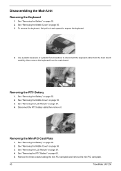
... "Removing the LCD Module" on page 52. 2. Remove the three screws holding the mini PCI card plate and remove the mini PCI card plate. 63 TravelMate 240/ 250 Disassembling the Main Unit Removing the Keyboard 1. See "Removing the Battery" on page 57. 4. See "Removing the Middle Cover" on page 56. 3.
... "Removing the LCD Module" on page 52. 2. Remove the three screws holding the mini PCI card plate and remove the mini PCI card plate. 63 TravelMate 240/ 250 Disassembling the Main Unit Removing the Keyboard 1. See "Removing the Battery" on page 57. 4. See "Removing the Middle Cover" on page 56. 3.
TravelMate 240/250 Service Guide
Page 153
... 19 package 19 type 19 D DC-AC LCD Inverter 27 DC-DC/Charger 26 DIMM 20 Combinations 20 package 20 Speed 20 voltage 20 Disassembly Machine 48, 74 Disassembly Flowchart 50 Display 1 display hotkeys 16 Display Standby Mode 29 DMA Channel Assignment 33 DVD-ROM Interface 22 E Environmental Requirements 29 Error Symptom... Check 95 F Features 1 Flash Utility 46 Floppy Disk Drive Interface 21 FRU (Field Replaceable Unit) List 112 H Hard disk 19, 21 Hard Disk Drive Module Disassembly 55 Hard Disk Standby Mode 29 Hardware Specifications and Configurations 19 HDD 19, 21 Hibernation Mode 29 144
... 19 package 19 type 19 D DC-AC LCD Inverter 27 DC-DC/Charger 26 DIMM 20 Combinations 20 package 20 Speed 20 voltage 20 Disassembly Machine 48, 74 Disassembly Flowchart 50 Display 1 display hotkeys 16 Display Standby Mode 29 DMA Channel Assignment 33 DVD-ROM Interface 22 E Environmental Requirements 29 Error Symptom... Check 95 F Features 1 Flash Utility 46 Floppy Disk Drive Interface 21 FRU (Field Replaceable Unit) List 112 H Hard disk 19, 21 Hard Disk Drive Module Disassembly 55 Hard Disk Standby Mode 29 Hardware Specifications and Configurations 19 HDD 19, 21 Hibernation Mode 29 144
TravelMate 240/250 Service Guide
Page 154
... 32 J Jumper and Connector Locations 108 SW1 Settings 110 K Keyboard 19, 26 Keyboard or Auxiliary Input Device Check 95 L L2 cache 19 LCD 27 M Machine Disassembly 48, 74 Mechanical Specification 29 media access on indicator 12 Memory Address Map 30 Memory Address Map 30 Memory Check 96 Modem 21 N Notebook Manager...
... 32 J Jumper and Connector Locations 108 SW1 Settings 110 K Keyboard 19, 26 Keyboard or Auxiliary Input Device Check 95 L L2 cache 19 LCD 27 M Machine Disassembly 48, 74 Mechanical Specification 29 media access on indicator 12 Memory Address Map 30 Memory Address Map 30 Memory Check 96 Modem 21 N Notebook Manager...


