TravelMate 240/250 Service Guide
Page 13
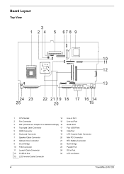
... FDD Connector 23 11 Launch Cable Connector 24 12 PCMCIA Slot 25 13 LCD Inverter Cable Connector Line-in Port Line-out Port RJ45+RJ11 Four USB Ports VGA Port LCD Coaxial Cable Connector Mini PCI Connector RTC Battery Connector North Bridge Parallel Port DC-in Port LCD Lid Switch 4 TravelMate 240/ 250
... FDD Connector 23 11 Launch Cable Connector 24 12 PCMCIA Slot 25 13 LCD Inverter Cable Connector Line-in Port Line-out Port RJ45+RJ11 Four USB Ports VGA Port LCD Coaxial Cable Connector Mini PCI Connector RTC Battery Connector North Bridge Parallel Port DC-in Port LCD Lid Switch 4 TravelMate 240/ 250
TravelMate 240/250 Service Guide
Page 36
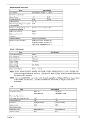
... backlight user, and is also responsible for the control of LCD brightness. Avoid touching the DC-AC inverter area while the system unit is an EEPROM in the inverter, which stores its supported LCD type and ID code. LCD Item Vendor & model name Mechanical Specifications LCD...~0A) 12.5V 11.5V Over Current Protection OCP (Over Current Protection, A) OVP (Over Voltage Protection, V) UVP (Under Voltage Protection, V) DC-AC LCD Inverter Item Vendor & model name Input voltage (V) Input current (mA) Output voltage (Vrms, no load) Output voltage frequency (kHz) Output Current/Lamp Ambit 8 ~...
... backlight user, and is also responsible for the control of LCD brightness. Avoid touching the DC-AC inverter area while the system unit is an EEPROM in the inverter, which stores its supported LCD type and ID code. LCD Item Vendor & model name Mechanical Specifications LCD...~0A) 12.5V 11.5V Over Current Protection OCP (Over Current Protection, A) OVP (Over Voltage Protection, V) UVP (Under Voltage Protection, V) DC-AC LCD Inverter Item Vendor & model name Input voltage (V) Input current (mA) Output voltage (Vrms, no load) Output voltage frequency (kHz) Output Current/Lamp Ambit 8 ~...

TravelMate 240/250 Service Guide
Page 60
LCD Module 4 LCD Cushions *4 LCD Bezel *1 Inverter *4 LCD LCD Panel LCD Coaxial Cable *4 LCD Brackets Screw List Item A B C D E F G H I J Description SCREW MAC FLAT M2.5*L4 NI NYLOK (86.00123.630) SCREW M2.0*L10 NYLOK(86.9A352.100) SCREW M2*3 NYLON 1JMCPC420325(86.9A352.3R0) SCREW M2.5X6(86.9A353.6R0) SCREW M3x4 (86.9A524.4R0) SCREW M2X2.0 (86.9A552.2R0) SCREW WAFER NYLOK NI 2ML3 (86.9A552.3R0) SCRW M2*4 WAFER NI (86.9A552.4R0) SCRW M2.5*3 WAFER NI (86.9A553.3R0) SCREW M2.5*4L NI (86.9A553.4R0) 51 TravelMate 240/ 250
LCD Module 4 LCD Cushions *4 LCD Bezel *1 Inverter *4 LCD LCD Panel LCD Coaxial Cable *4 LCD Brackets Screw List Item A B C D E F G H I J Description SCREW MAC FLAT M2.5*L4 NI NYLOK (86.00123.630) SCREW M2.0*L10 NYLOK(86.9A352.100) SCREW M2*3 NYLON 1JMCPC420325(86.9A352.3R0) SCREW M2.5X6(86.9A353.6R0) SCREW M3x4 (86.9A524.4R0) SCREW M2X2.0 (86.9A552.2R0) SCREW WAFER NYLOK NI 2ML3 (86.9A552.3R0) SCRW M2*4 WAFER NI (86.9A552.4R0) SCRW M2.5*3 WAFER NI (86.9A553.3R0) SCREW M2.5*4L NI (86.9A553.4R0) 51 TravelMate 240/ 250

TravelMate 240/250 Service Guide
Page 66
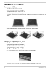
.... Removing the LCD Module 1. two on the right and two on page 52. 2. Remove the four screws holding the LCD hinge; Then disconnect the LCD inverter cable. 5. two on the right and two on the bottom; Remove the two screws on the left . 7. Then you can remove the entire LCD module...; one on the right and the other on page 56. 3. Remove the two screws and then detach the launch board from the main unit. 57 TravelMate 240/ 250 See "Removing the Launch Board" on page 56. 4.
.... Removing the LCD Module 1. two on the right and two on page 52. 2. Remove the four screws holding the LCD hinge; Then disconnect the LCD inverter cable. 5. two on the right and two on the bottom; Remove the two screws on the left . 7. Then you can remove the entire LCD module...; one on the right and the other on page 56. 3. Remove the two screws and then detach the launch board from the main unit. 57 TravelMate 240/ 250 See "Removing the Launch Board" on page 56. 4.
TravelMate 240/250 Service Guide
Page 68
... Battery" on page 56. 4. Snap off the bezel carefully, and then remove the LCD bezel from the inverter board. 7. See "Removing the Launch Board" on page 52. 2. To remove the inverter board, first remove one screw from the LCD module. See "Removing the Launch Board" on page 52. ... the LCD Module" on page 59. 6. Disassembling the LCD Module Removing the LCD Bezel 1. Disconnect the LCD power cable then disconnect the inverter cable from the inverter board. 59 TravelMate 240/ 250 See "Removing the LCD Bezel" on page 57. 5. See "Removing the Middle Cover" on page 56. 3.
... Battery" on page 56. 4. Snap off the bezel carefully, and then remove the LCD bezel from the inverter board. 7. See "Removing the Launch Board" on page 52. 2. To remove the inverter board, first remove one screw from the LCD module. See "Removing the Launch Board" on page 52. ... the LCD Module" on page 59. 6. Disassembling the LCD Module Removing the LCD Bezel 1. Disconnect the LCD power cable then disconnect the inverter cable from the inverter board. 59 TravelMate 240/ 250 See "Removing the LCD Bezel" on page 57. 5. See "Removing the Middle Cover" on page 56. 3.

TravelMate 240/250 Service Guide
Page 69
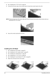
Removing the 15" TFT LCD 1. See "Removing the Launch Board" on page 57. 5. See "Removing the LCD Module" on page 56. 4. See "Removing the Inverter Board (15" LCD)" on page 59. 6. Removing the LCD Brackets 1. See "Removing the LCD Bezel" on page 59. 7. Then take the LCD out of the ... the LCD, first remove the four screws that secure the LCD hinges. 8. See "Removing the Middle Cover" on page 56. 3. NOTE: Please arrange the LCD inverter cable well to the LCD panel as the picture below shows when you reassemble the LCD module.
Removing the 15" TFT LCD 1. See "Removing the Launch Board" on page 57. 5. See "Removing the LCD Module" on page 56. 4. See "Removing the Inverter Board (15" LCD)" on page 59. 6. Removing the LCD Brackets 1. See "Removing the LCD Bezel" on page 59. 7. Then take the LCD out of the ... the LCD, first remove the four screws that secure the LCD hinges. 8. See "Removing the Middle Cover" on page 56. 3. NOTE: Please arrange the LCD inverter cable well to the LCD panel as the picture below shows when you reassemble the LCD module.
TravelMate 240/250 Service Guide
Page 70
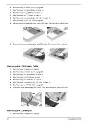
See "Removing the Inverter Board (15" LCD)" on page 56. 3. Remove the four screws holding the left bracket.. Removing the ...on page 52. 2. See "Removing the Battery" on page 57. 5. See "Removing the LCD Bezel" on page 59. 7. See "Removing the Inverter Board (15" LCD)" on page 59. 6. See "Removing the 15" TFT LCD" on page 56. 4. Removing the LCD Hinges 1. See .... See "Removing the Battery" on page 56. 3. 2. See "Removing the Middle Cover" on page 52. 61 TravelMate 240/ 250 Tear off the mylar fastening the LCD coaxial cable, then disconnect the coaxial cable.
See "Removing the Inverter Board (15" LCD)" on page 56. 3. Remove the four screws holding the left bracket.. Removing the ...on page 52. 2. See "Removing the Battery" on page 57. 5. See "Removing the LCD Bezel" on page 59. 7. See "Removing the Inverter Board (15" LCD)" on page 59. 6. See "Removing the 15" TFT LCD" on page 56. 4. Removing the LCD Hinges 1. See .... See "Removing the Battery" on page 56. 3. 2. See "Removing the Middle Cover" on page 52. 61 TravelMate 240/ 250 Tear off the mylar fastening the LCD coaxial cable, then disconnect the coaxial cable.

TravelMate 240/250 Service Guide
Page 71
Remove the screw holding the left hinge, then remove the left hinge. Remove the screw holding the right hinge, then remove the right hinge. 9. See "Removing the LCD Module" on page 60. 8. See "Removing the 15" TFT LCD" on page 57. 5. See "Removing the Middle Cover" on page 59. 7. See "Removing the Inverter Board (15" LCD)" on page 56. 3. See "Removing the LCD Bezel" on page 56. 4. Chapter 3 62 See "Removing the Launch Board" on page 59. 6. 2.
Remove the screw holding the left hinge, then remove the left hinge. Remove the screw holding the right hinge, then remove the right hinge. 9. See "Removing the LCD Module" on page 60. 8. See "Removing the 15" TFT LCD" on page 57. 5. See "Removing the Middle Cover" on page 59. 7. See "Removing the Inverter Board (15" LCD)" on page 56. 3. See "Removing the LCD Bezel" on page 56. 4. Chapter 3 62 See "Removing the Launch Board" on page 59. 6. 2.

TravelMate 240/250 Service Guide
Page 93
.... See "Installing the LCD Hinges" on page 95. 2. Fasten the right hinge with four screws. See "Installing the LCD Brackets" on page 95. 3. Installing the Inverter Board (15" LCD) 1. See "Installing the LCD Coaxial Cable" on page 95. 4. 4. Attach the right bracket to the LCD panel. 5. Secure the left hinge with...
.... See "Installing the LCD Hinges" on page 95. 2. Fasten the right hinge with four screws. See "Installing the LCD Brackets" on page 95. 3. Installing the Inverter Board (15" LCD) 1. See "Installing the LCD Coaxial Cable" on page 95. 4. 4. Attach the right bracket to the LCD panel. 5. Secure the left hinge with...
TravelMate 240/250 Service Guide
Page 94
... LCD bezel to the LCD panel as the picture below shows when you reassemble the LCD module. 6. NOTE: Please arrange the LCD inverter cable well to the LCD module. 85 TravelMate 240/ 250 See "Installing the LCD Hinges" on page 96. 6. See "Installing the LCD Coaxial Cable" on page 95. 4. ...4. See "Installing the LCD Brackets" on page 95. 3. Connect the inverter cable to the LCD. See "Installing the 15" TFT LCD" on page 96. ...
... LCD bezel to the LCD panel as the picture below shows when you reassemble the LCD module. 6. NOTE: Please arrange the LCD inverter cable well to the LCD module. 85 TravelMate 240/ 250 See "Installing the LCD Hinges" on page 96. 6. See "Installing the LCD Coaxial Cable" on page 95. 4. ...4. See "Installing the LCD Brackets" on page 95. 3. Connect the inverter cable to the LCD. See "Installing the 15" TFT LCD" on page 96. ...
TravelMate 240/250 Service Guide
Page 96
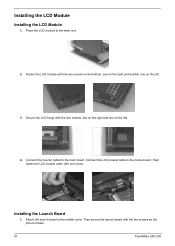
... module with one on the bottom; one on the right and another one screw. Connect the inverter cablet to the maine board. Secure the LCD hinge with the two screws as the picture shows. 87 TravelMate 240/ 250 Connect the LCD coaxial cable to the main board. Attach the launch board to the...
... module with one on the bottom; one on the right and another one screw. Connect the inverter cablet to the maine board. Secure the LCD hinge with the two screws as the picture shows. 87 TravelMate 240/ 250 Connect the LCD coaxial cable to the main board. Attach the launch board to the...

TravelMate 240/250 Service Guide
Page 111
... indicator turns off and LCD is blank. Reconnect the DIMM. See "Power System Check" on page 96. Reconnect the LCD connector Hard disk drive LCD inverter ID LCD cable LCD Inverter LCD System board No beep, power-on indicator turns on LCD during POST but system runs correctly. LCD... inverter ID LCD cable LCD inverter LCD System board No beep, power-on indicator turns on and a blinking cursor shown on and LCD is blank. LED board. Power source (battery pack ...
... indicator turns off and LCD is blank. Reconnect the DIMM. See "Power System Check" on page 96. Reconnect the LCD connector Hard disk drive LCD inverter ID LCD cable LCD Inverter LCD System board No beep, power-on indicator turns on LCD during POST but system runs correctly. LCD... inverter ID LCD cable LCD inverter LCD System board No beep, power-on indicator turns on and a blinking cursor shown on and LCD is blank. LED board. Power source (battery pack ...

TravelMate 240/250 Service Guide
Page 112
... the LCD connector LCD inverter ID LCD cable LCD inverter LCD System board LCD inverter ID LCD inverter LCD cable LCD System board Indicator-Related Symptoms Symptom / Error Action in Sequence Indicator incorrectly remains off . Hold and press the power switch for more than 4 seconds. Battery pack System board 103 TravelMate 240/ 250 Battery pack Power...
... the LCD connector LCD inverter ID LCD cable LCD inverter LCD System board LCD inverter ID LCD inverter LCD cable LCD System board Indicator-Related Symptoms Symptom / Error Action in Sequence Indicator incorrectly remains off . Hold and press the power switch for more than 4 seconds. Battery pack System board 103 TravelMate 240/ 250 Battery pack Power...

TravelMate 240/250 Service Guide
Page 130
Picture No. Partname And Description INVERTER CABLE Part Number 50.T30V1.007 LCD COAXIAL CABLE 50.T30V1.008 NS LCD PANEL W/HINGE & LOGO 60.T30V1.008 Main Board Miscellaneous 121 NS LCD BEZEL 14.1" W/ICON LABEL 60.T30V1.006 LCD BEZEL 15" W/ICON LABEL 60.T30V1.007 HINGE PACK 6K.T30V1.001 MAINBOARD W/LAUNCH CABLE & MODEM & MODEM CABLE & PCMCIA SLOT & RTC BATTERY MB.T3001.001 LOGO 31.42S08.001 ICON LABEL TOUCHPAD SCROLL KEY 40.T30V1.001 42.T30V1.007 TravelMate 240/250
Picture No. Partname And Description INVERTER CABLE Part Number 50.T30V1.007 LCD COAXIAL CABLE 50.T30V1.008 NS LCD PANEL W/HINGE & LOGO 60.T30V1.008 Main Board Miscellaneous 121 NS LCD BEZEL 14.1" W/ICON LABEL 60.T30V1.006 LCD BEZEL 15" W/ICON LABEL 60.T30V1.007 HINGE PACK 6K.T30V1.001 MAINBOARD W/LAUNCH CABLE & MODEM & MODEM CABLE & PCMCIA SLOT & RTC BATTERY MB.T3001.001 LOGO 31.42S08.001 ICON LABEL TOUCHPAD SCROLL KEY 40.T30V1.001 42.T30V1.007 TravelMate 240/250
TravelMate 240/250 Service Guide
Page 153
... 12, 13 contrast hotkeys 16 Controllers 19 Index Index Core logic 19 CPU core voltage 19 I/O voltage 19 package 19 type 19 D DC-AC LCD Inverter 27 DC-DC/Charger 26 DIMM 20 Combinations 20 package 20 Speed 20 voltage 20 Disassembly Machine 48, 74 Disassembly Flowchart 50 Display 1 display hotkeys...
... 12, 13 contrast hotkeys 16 Controllers 19 Index Index Core logic 19 CPU core voltage 19 I/O voltage 19 package 19 type 19 D DC-AC LCD Inverter 27 DC-DC/Charger 26 DIMM 20 Combinations 20 package 20 Speed 20 voltage 20 Disassembly Machine 48, 74 Disassembly Flowchart 50 Display 1 display hotkeys...


