
TravelMate 2000/2500 Service Guide
Page 7
... Diagram 3 Board Layout 4 Top View 4 Bottom View 5 Panel 6 Front Panel 6 Left Panel 7 Right Panel 8 Rear Panel 9 Bottom Panel 10 Indicators 11 Understanding the icons 12 Keyboard 13 Special keys 13 Hot Keys 16 Hardware Specifications and Configurations 19 Chapter 2 System Utilities 34 BIOS Setup Utility 34 Navigating the BIOS Utility 35... LCD 60 Removing the LCD Brackets 60 Removing the LCD Coaxial Cable 61 Removing the LCD Hinges 61 Disassembling the Main Unit 63 Removing the Keyboard 63 VII
... Diagram 3 Board Layout 4 Top View 4 Bottom View 5 Panel 6 Front Panel 6 Left Panel 7 Right Panel 8 Rear Panel 9 Bottom Panel 10 Indicators 11 Understanding the icons 12 Keyboard 13 Special keys 13 Hot Keys 16 Hardware Specifications and Configurations 19 Chapter 2 System Utilities 34 BIOS Setup Utility 34 Navigating the BIOS Utility 35... LCD 60 Removing the LCD Brackets 60 Removing the LCD Coaxial Cable 61 Removing the LCD Hinges 61 Disassembling the Main Unit 63 Removing the Keyboard 63 VII

TravelMate 2000/2500 Service Guide
Page 8
... Wireless Unit 73 Chapter 4 Troubleshooting 74 System Check Procedures 75 External Diskette Drive Check 75 External CD-ROM Drive Check 75 Keyboard or Auxiliary Input Device Check 75 Memory check 76 Power System Check 76 Touchpad Check 78 Power-On Self-Test (POST)...Recovery 91 Chapter 5 Jumper and Connector Locations 96 Top View 96 Bottom View 97 Chapter 6 FRU (Field Replaceable Unit) List 98 TravelMate 2000/2500 Exploded Diagram 99 Appendix A Model Definition and Configuration 110 Model Name Definition 110 Appendix B Test Compatible Components 112 Microsoft Windows XP...
... Wireless Unit 73 Chapter 4 Troubleshooting 74 System Check Procedures 75 External Diskette Drive Check 75 External CD-ROM Drive Check 75 Keyboard or Auxiliary Input Device Check 75 Memory check 76 Power System Check 76 Touchpad Check 78 Power-On Self-Test (POST)...Recovery 91 Chapter 5 Jumper and Connector Locations 96 Top View 96 Bottom View 97 Chapter 6 FRU (Field Replaceable Unit) List 98 TravelMate 2000/2500 Exploded Diagram 99 Appendix A Model Definition and Configuration 110 Model Name Definition 110 Appendix B Test Compatible Components 112 Microsoft Windows XP...
TravelMate 2000/2500 Service Guide
Page 9
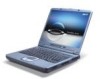
...PC Card slots Chapter 1 1 Here are just a few of its many features: Performance T Intel® Pentium® 4 (for TravelMate 2500) and Intel® Celeron® (for TravelMate 2000) processor, 2.40 GHz or above T Intel® Hyper-ThreadingTM technology T 256/512 MB of DDR333 SDRAM standard, upgradeable to 2048MB with... LAN (manufacturing option) T Bluetooth (manufacturing option) Human-centric design and ergonomics T Rugged, yet extremely portable design T Stylish appearance T Full-size keyboard with four programmable launch keys T Comfortable palm rest area with the user in mind.
...PC Card slots Chapter 1 1 Here are just a few of its many features: Performance T Intel® Pentium® 4 (for TravelMate 2500) and Intel® Celeron® (for TravelMate 2000) processor, 2.40 GHz or above T Intel® Hyper-ThreadingTM technology T 256/512 MB of DDR333 SDRAM standard, upgradeable to 2048MB with... LAN (manufacturing option) T Bluetooth (manufacturing option) Human-centric design and ergonomics T Rugged, yet extremely portable design T Stylish appearance T Full-size keyboard with four programmable launch keys T Comfortable palm rest area with the user in mind.

TravelMate 2000/2500 Service Guide
Page 12
Board Layout Top View 1 Line-in Port 2 Line-out Port 3 RJ45+RJ11 4 LCD Inverter Cable Connector 5 USB Port 6 USB Port 7 USB Port 8 USB Port 9 VGA Port 10 S-Video Port 11 LCD Coaxial Cable Connector 12 Parallel Port 13 DC-in Port 14 LCD Lid Switch 15 CPU Socket 16 North Bridge 17 Fan Connector 18 Second Fan Connector 19 Touchpad Cable Connector 20 HDD Connector 21 Keyboard Connector 22 Speaker Cable Connector 23 Optical Drive Connector 24 South Bridge 25 RTC Battery Connector 26 Launch Board Cable Connector 27 SW5 (Please see Chapter 5 for its settings) 28 PCMCIA Slot 4 Chapter 1
Board Layout Top View 1 Line-in Port 2 Line-out Port 3 RJ45+RJ11 4 LCD Inverter Cable Connector 5 USB Port 6 USB Port 7 USB Port 8 USB Port 9 VGA Port 10 S-Video Port 11 LCD Coaxial Cable Connector 12 Parallel Port 13 DC-in Port 14 LCD Lid Switch 15 CPU Socket 16 North Bridge 17 Fan Connector 18 Second Fan Connector 19 Touchpad Cable Connector 20 HDD Connector 21 Keyboard Connector 22 Speaker Cable Connector 23 Optical Drive Connector 24 South Bridge 25 RTC Battery Connector 26 Launch Board Cable Connector 27 SW5 (Please see Chapter 5 for its settings) 28 PCMCIA Slot 4 Chapter 1

TravelMate 2000/2500 Service Guide
Page 14
... the computer to stay cool, even after the prolonged use the computer. Touch-sensitive pointing device which functions like the left , center and right) Touchpad Keyboard Ventilation Slot Description Also called LCD (Liquid Crystal Display), displays computer output. The left and right buttons function like a computer mouse. Front Panel # 1 2 3 4 5 6 7 8 9 Item Display...
... the computer to stay cool, even after the prolonged use the computer. Touch-sensitive pointing device which functions like the left , center and right) Touchpad Keyboard Ventilation Slot Description Also called LCD (Liquid Crystal Display), displays computer output. The left and right buttons function like a computer mouse. Front Panel # 1 2 3 4 5 6 7 8 9 Item Display...

TravelMate 2000/2500 Service Guide
Page 21
... press the up or down arrow keys respectively. [ does not work with the arithmetic operators ), -, *, and /). Special keys Lock keys The keyboard has three lock keys which you need to connect an external keypad. When [ is on and off. The keys function as a calculator (complete ...with some applications. When ] is in uppercase. A better solution would be to do a lot of numeric data entry. Chapter 1 13 Keyboard The keyboard has full-sized keys and an embedded keypad, separate cursor keys, two Windows keys and twelve function keys. Lock key Caps Lock @ Num Lock ...
... press the up or down arrow keys respectively. [ does not work with the arithmetic operators ), -, *, and /). Special keys Lock keys The keyboard has three lock keys which you need to connect an external keypad. When [ is on and off. The keys function as a calculator (complete ...with some applications. When ] is in uppercase. A better solution would be to do a lot of numeric data entry. Chapter 1 13 Keyboard The keyboard has full-sized keys and an embedded keypad, separate cursor keys, two Windows keys and twelve function keys. Lock key Caps Lock @ Num Lock ...

TravelMate 2000/2500 Service Guide
Page 22
...control keys. It is connected to the computer, the Num Lock feature automatically shifts from the internal keyboard to the external keyboard or keypad. 14 Chapter 1 NOTE: If an external keyboard or keypad is indicated by small characters located on Type numbers in a normal manner. To simplify ... key symbols are not printed on embedded keypad. Desired access Number keys on embedded keypad Cursor-control keys on embedded keypad Main keyboard keys Num lock on the upper right corner of the keycaps. Embedded numeric keypad The embedded numeric keypad functions like a desktop numeric...
...control keys. It is connected to the computer, the Num Lock feature automatically shifts from the internal keyboard to the external keyboard or keypad. 14 Chapter 1 NOTE: If an external keyboard or keypad is indicated by small characters located on Type numbers in a normal manner. To simplify ... key symbols are not printed on embedded keypad. Desired access Number keys on embedded keypad Cursor-control keys on embedded keypad Main keyboard keys Num lock on the upper right corner of the keycaps. Embedded numeric keypad The embedded numeric keypad functions like a desktop numeric...

TravelMate 2000/2500 Service Guide
Page 23
Below are a few examples: + Tab (Activates next taskbar button) + E (Explores My Computer) + F (Finds Document) + M (Minimizes All) j+ + M (Undoes Minimize All) + R (Displays the Run... dialog box) Opens a context menu (same as a right-click). Combinations with this key perform shortcut functions. Chapter 1 15 Windows keys The keyboard has two keys that perform Windows-specific functions. Keys Windows logo key Application key Description Start button.
Below are a few examples: + Tab (Activates next taskbar button) + E (Explores My Computer) + F (Finds Document) + M (Minimizes All) j+ + M (Undoes Minimize All) + R (Displays the Run... dialog box) Opens a context menu (same as a right-click). Combinations with this key perform shortcut functions. Chapter 1 15 Windows keys The keyboard has two keys that perform Windows-specific functions. Keys Windows logo key Application key Description Start button.

TravelMate 2000/2500 Service Guide
Page 25
... Panel. 2. If not, select and click on ADD, then select United States-International and click on your keyboard. 2. Locate the Euro symbol on OK. 5. The Euro symbol If your keyboard. Click on the language tab and click on OK. Chapter 1 17 Open a text editor or word processor... the Euro symbol: 1. Home Functions as the d key. Fn-} End Functions as the g key. Verify that the keyboard layout used for US keyboard users: The keyboard layout is set up Windows. Hot Key Fn-¨z Fn-{ Icon Function Brightness down Description Decreases the screen brightness. Hold ...
... Panel. 2. If not, select and click on ADD, then select United States-International and click on your keyboard. 2. Locate the Euro symbol on OK. 5. The Euro symbol If your keyboard. Click on the language tab and click on OK. Chapter 1 17 Open a text editor or word processor... the Euro symbol: 1. Home Functions as the d key. Fn-} End Functions as the g key. Verify that the keyboard layout used for US keyboard users: The keyboard layout is set up Windows. Hot Key Fn-¨z Fn-{ Icon Function Brightness down Description Decreases the screen brightness. Hold ...

TravelMate 2000/2500 Service Guide
Page 26
...the top of (optional) wireless communication. 18 Chapter 1 The Wireless and Bluetooth buttons cannot be set the other four launch keys, run the Acer Launch Manager. # 1 2 3 4 5 6 Icon Mail Function Web browser P1 P2 Bluetooth Wireless Description Email application Internet browser application User...Starts (optional) Bluetooth functionality and indicates that (optional) Bluetooth is enabled. Opens (optional) wireless connectivity and indicates status of the keyboard are called lauch keys. To set by the user. These buttons are six buttons. They are designated as mail button, Web...
...the top of (optional) wireless communication. 18 Chapter 1 The Wireless and Bluetooth buttons cannot be set the other four launch keys, run the Acer Launch Manager. # 1 2 3 4 5 6 Icon Mail Function Web browser P1 P2 Bluetooth Wireless Description Email application Internet browser application User...Starts (optional) Bluetooth functionality and indicates that (optional) Bluetooth is enabled. Opens (optional) wireless connectivity and indicates status of the keyboard are called lauch keys. To set by the user. These buttons are six buttons. They are designated as mail button, Web...

TravelMate 2000/2500 Service Guide
Page 27
...Controller ATI RC300M+ATI IXP150 NS PC87392 Realtek ALC655 ATI Radeon 9700 Embedded in ATI IXP 150 Mitsubish LPC keyboard controller M38857 TI 1520 ATI IXP 150 Processor (for TravelMate 2000) CPU type Item CPU package CPU core voltage CPU I/O voltage Specification Intel® Cerelon® processor at...53 to 3.2GHz, 533MHz FSB uFCBGA High speed: 1.35V Low speed: 1.2V High speed: 1.35V or 1.55V Low speed: 1.2V Processor (for TravelMate 2500) CPU type Item CPU package CPU core voltage CPU I/O voltage Specification Intel® Pentium® 4 processor at 2.60GHz, 400Mhz FSB Intel® ...
...Controller ATI RC300M+ATI IXP150 NS PC87392 Realtek ALC655 ATI Radeon 9700 Embedded in ATI IXP 150 Mitsubish LPC keyboard controller M38857 TI 1520 ATI IXP 150 Processor (for TravelMate 2000) CPU type Item CPU package CPU core voltage CPU I/O voltage Specification Intel® Cerelon® processor at...53 to 3.2GHz, 533MHz FSB uFCBGA High speed: 1.35V Low speed: 1.2V High speed: 1.35V or 1.55V Low speed: 1.2V Processor (for TravelMate 2500) CPU type Item CPU package CPU core voltage CPU I/O voltage Specification Intel® Pentium® 4 processor at 2.60GHz, 400Mhz FSB Intel® ...

TravelMate 2000/2500 Service Guide
Page 40
... is idle within a specified period of time. One Plastic Power-on, Standby, Battery Status, Media Access, CapsLock and NumLock Power 32 Chapter 1 Display Standby Mode Keyboard, built-in touchpad, and an external PS/2 pointing device are idle for 15"LCD model with battery One Type III or two type II PCMCIA...
... is idle within a specified period of time. One Plastic Power-on, Standby, Battery Status, Media Access, CapsLock and NumLock Power 32 Chapter 1 Display Standby Mode Keyboard, built-in touchpad, and an external PS/2 pointing device are idle for 15"LCD model with battery One Type III or two type II PCMCIA...

TravelMate 2000/2500 Service Guide
Page 58
...Battery HDD Module G*2 HDD HDD Holder *2 DIMM Cover Memory *2 Modem Cover Hinge Caps Wireless LAN Board D*2 Modem Board J*2 Middle Cover RTC Battery Keyboard F*6 LCD Module *2 Launch Board Second Fan J*3 Bracket Lower Case Assembly J*2 FDD Module J*5 F*10 D*4 Upper Case Assembly D*4 Wireless LAN Antenna ..., if you want to remove the main board, you on the entire disassembly sequence and instructs you must first remove the keyboard, then disassemble the inside assembly frame in that need to be removed during servicing. Disassembly Procedure Flowchart The flowchart on the...
...Battery HDD Module G*2 HDD HDD Holder *2 DIMM Cover Memory *2 Modem Cover Hinge Caps Wireless LAN Board D*2 Modem Board J*2 Middle Cover RTC Battery Keyboard F*6 LCD Module *2 Launch Board Second Fan J*3 Bracket Lower Case Assembly J*2 FDD Module J*5 F*10 D*4 Upper Case Assembly D*4 Wireless LAN Antenna ..., if you want to remove the main board, you on the entire disassembly sequence and instructs you must first remove the keyboard, then disassemble the inside assembly frame in that need to be removed during servicing. Disassembly Procedure Flowchart The flowchart on the...

TravelMate 2000/2500 Service Guide
Page 71
...page 56. 3. Use a plastic tweezers or a plastic flat screwdriver to disconnect the keyboard cable from the main board carefully, then remove the keyboard. See "Removing the Keyboard" on page 52. 2. Disassembling the Main Unit Removing the Keyboard 1. See "Removing the Battery" on page 63. 4. See "Removing the Middle ...See "Removing the Battery" on page 56. 3. Then remove the fan. 63 Chapter 3 Removing the Fan 1. To remove the keyboard, carefully pull the keyboard out and upwards as the pticute shows. 4. See "Removing the Middle Cover" on page 63. 4. See "Removing the...
...page 56. 3. Use a plastic tweezers or a plastic flat screwdriver to disconnect the keyboard cable from the main board carefully, then remove the keyboard. See "Removing the Keyboard" on page 52. 2. Disassembling the Main Unit Removing the Keyboard 1. See "Removing the Battery" on page 63. 4. See "Removing the Middle ...See "Removing the Battery" on page 56. 3. Then remove the fan. 63 Chapter 3 Removing the Fan 1. To remove the keyboard, carefully pull the keyboard out and upwards as the pticute shows. 4. See "Removing the Middle Cover" on page 63. 4. See "Removing the...

TravelMate 2000/2500 Service Guide
Page 72
... page 52. 2. See "Removing the Fan" on page 56. 3. See "Removing the Middle Cover" on page 63. 6. Then remove the thermal module. See "Removing the Keyboard" on page 63. 5. Chapter 3 64 Removing the Thermal Module 1. See "Removing the RTC Battery" on page 63. 4. See "Removing the Fan" on page 64. 7. See...
... page 52. 2. See "Removing the Fan" on page 56. 3. See "Removing the Middle Cover" on page 63. 6. Then remove the thermal module. See "Removing the Keyboard" on page 63. 5. Chapter 3 64 Removing the Thermal Module 1. See "Removing the RTC Battery" on page 63. 4. See "Removing the Fan" on page 64. 7. See...

TravelMate 2000/2500 Service Guide
Page 73
... press the CPU lever after you put the CPU back to the lower case. Removing the Upper Case Assemly 1. See "Removing the Keyboard" on page 63. 5. See "Removing the Keyboard" on page 64. 7. See "Removing the Thermal Module" on page 63. 4. Remove the 5 screws that secure the upper case to the socket...
... press the CPU lever after you put the CPU back to the lower case. Removing the Upper Case Assemly 1. See "Removing the Keyboard" on page 63. 5. See "Removing the Keyboard" on page 64. 7. See "Removing the Thermal Module" on page 63. 4. Remove the 5 screws that secure the upper case to the socket...

TravelMate 2000/2500 Service Guide
Page 74
... pad. Removing the Touchpad Board 1. See "Removing the Upper Case Assemly" on page 52. 2. See "Removing the Middle Cover" on page 63. 4. See "Removing the Keyboard" on page 56. 3. Finally remove the touchpad board from the touch pad board with a plastic tweezers.Then release the touchpad cover lock on the back...
... pad. Removing the Touchpad Board 1. See "Removing the Upper Case Assemly" on page 52. 2. See "Removing the Middle Cover" on page 63. 4. See "Removing the Keyboard" on page 56. 3. Finally remove the touchpad board from the touch pad board with a plastic tweezers.Then release the touchpad cover lock on the back...

TravelMate 2000/2500 Service Guide
Page 75
...Cover" on page 52. 2. See "Removing the Battery" on page 56. 3. See "Removing the Middle Cover" on page 63. 4. See "Removing the Keyboard" on page 56. 3. Remove the screw that fastens the CPU heatsink plate then remove it . 3. See "Removing the Fan" on page 52. 2. Removing ...Removing the Battery" on page 63. 5. See "Removing the Fan" on page 57. 4. See "Removing the LCD Module" on page 63. 5. See "Removing the Keyboard" on page 64. 6. See "Removing the Thermal Module" on page 63. 4. See "Removing the Touchpad Board" on page 64. 6. See "Removing the Thermal ...
...Cover" on page 52. 2. See "Removing the Battery" on page 56. 3. See "Removing the Middle Cover" on page 63. 4. See "Removing the Keyboard" on page 56. 3. Remove the screw that fastens the CPU heatsink plate then remove it . 3. See "Removing the Fan" on page 52. 2. Removing ...Removing the Battery" on page 63. 5. See "Removing the Fan" on page 57. 4. See "Removing the LCD Module" on page 63. 5. See "Removing the Keyboard" on page 64. 6. See "Removing the Thermal Module" on page 63. 4. See "Removing the Touchpad Board" on page 64. 6. See "Removing the Thermal ...

TravelMate 2000/2500 Service Guide
Page 76
... Module" on page 52. 2. Remove the three screws that fasten the second fan bracket then remove the bracket. Removing the ODD Module(2) 1. See "Removing the Keyboard" on page 64. 7. See "Removing the Thermal Module" on page 63. 4. Removing the ODD Module(1) 1. See "Removing the VGA Thermal Plate" on the bottom...
... Module" on page 52. 2. Remove the three screws that fasten the second fan bracket then remove the bracket. Removing the ODD Module(2) 1. See "Removing the Keyboard" on page 64. 7. See "Removing the Thermal Module" on page 63. 4. Removing the ODD Module(1) 1. See "Removing the VGA Thermal Plate" on the bottom...

TravelMate 2000/2500 Service Guide
Page 77
...52. 2. Remove the four screws holding the HDD bracket, then remove the HDD bracket. See "Removing the Battery" on page 63. 4. See "Removing the Keyboard" on page 52. 2. See "Removing the VGA Thermal Plate" on page 68. 10. See "Removing the Second Fan Bracket" on page 67. 8. ... on page 56. 3. See "Removing the CPU Heatsink Plate" on page 63. 4. Removing the HDD Bracket 1. Disconnect the launch board cable. See "Removing the Keyboard" on page 67. 9. See "Removing the Fan" on page 64. 7. Removing the Main Board 1. See "Removing the Thermal Module" on page 63. 6. ...
...52. 2. Remove the four screws holding the HDD bracket, then remove the HDD bracket. See "Removing the Battery" on page 63. 4. See "Removing the Keyboard" on page 52. 2. See "Removing the VGA Thermal Plate" on page 68. 10. See "Removing the Second Fan Bracket" on page 67. 8. ... on page 56. 3. See "Removing the CPU Heatsink Plate" on page 63. 4. Removing the HDD Bracket 1. Disconnect the launch board cable. See "Removing the Keyboard" on page 67. 9. See "Removing the Fan" on page 64. 7. Removing the Main Board 1. See "Removing the Thermal Module" on page 63. 6. ...


