Quick Start Guide
Page 1
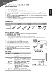
...indicates power on a stable and level workspace. 2 Remove the monitor from the packaging and place it on . Then tighten the thumbscrews on the signal cable D-SUB DC-IN connector. 3 Connect one end of the adapter to the monitor and the other end to a properly grounded, AC ...LCD monitor near a window. Blinking blue indicates standby / power saving mode. English Acer LCD Monitor Quick Start Guide (QSG) Important safety instructions Please read the following circumstances occur: • Monitor-to-PC signal cable is frayed or damaged. • Liquid spills onto the LCD monitor or...
...indicates power on a stable and level workspace. 2 Remove the monitor from the packaging and place it on . Then tighten the thumbscrews on the signal cable D-SUB DC-IN connector. 3 Connect one end of the adapter to the monitor and the other end to a properly grounded, AC ...LCD monitor near a window. Blinking blue indicates standby / power saving mode. English Acer LCD Monitor Quick Start Guide (QSG) Important safety instructions Please read the following circumstances occur: • Monitor-to-PC signal cable is frayed or damaged. • Liquid spills onto the LCD monitor or...
User Manual
Page 11
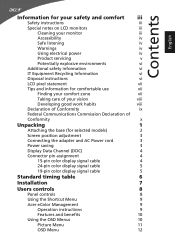
... 3 Power saving 3 Display Data Channel (DDC) 4 Connector pin assignment 4 15-pin color display signal cable 4 24-pin color display signal cable 5 19-pin color display signal cable 5 Standard timing table 6 Installation 7 Users controls 8 Panel controls 8 Using the Shortcut Menu 9 Acer eColor Management 9 Operation instructions 9 Features and benefits 10 Using the OSD Menus 10 Picture...
... 3 Power saving 3 Display Data Channel (DDC) 4 Connector pin assignment 4 15-pin color display signal cable 4 24-pin color display signal cable 5 19-pin color display signal cable 5 Standard timing table 6 Installation 7 Users controls 8 Panel controls 8 Using the Shortcut Menu 9 Acer eColor Management 9 Operation instructions 9 Features and benefits 10 Using the OSD Menus 10 Picture...
User Manual
Page 15
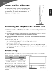
..." mode by the blinking blue light. Mode On Standby/Power saving LED light Blue Blinking Blue The power saving mode will be kept until a control signal has been detected or the keyboard or mouse is activated. LED indicator 3 No user-adjustment is required. • Plug one end of the AC power... cord to "on" is around 3 seconds. The recovery time from the display controller, as indicated by the control signal from "power saving" mode back to the Adapter, and plug the other end into an AC outlet. • For units using 120 V AC: Use a UL...
..." mode by the blinking blue light. Mode On Standby/Power saving LED light Blue Blinking Blue The power saving mode will be kept until a control signal has been detected or the keyboard or mouse is activated. LED indicator 3 No user-adjustment is required. • Plug one end of the AC power... cord to "on" is around 3 seconds. The recovery time from the display controller, as indicated by the control signal from "power saving" mode back to the Adapter, and plug the other end into an AC outlet. • For units using 120 V AC: Use a UL...
User Manual
Page 16
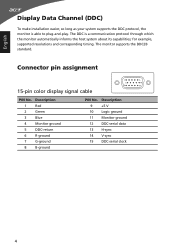
... able to plug-and-play. Description 1 Red 2 Green 3 Blue 4 Monitor ground 5 DDC-return 6 R-ground 7 G-ground 8 B-ground PIN No. Connector pin assignment 15-pin color display signal cable 1 5 6 10 11 15 PIN No. Description 9 +5 V 10 Logic ground 11 Monitor ground 12 DDC-serial data 13 H-sync 14 V-sync 15 DDC-serial clock...
... able to plug-and-play. Description 1 Red 2 Green 3 Blue 4 Monitor ground 5 DDC-return 6 R-ground 7 G-ground 8 B-ground PIN No. Connector pin assignment 15-pin color display signal cable 1 5 6 10 11 15 PIN No. Description 9 +5 V 10 Logic ground 11 Monitor ground 12 DDC-serial data 13 H-sync 14 V-sync 15 DDC-serial clock...
User Manual
Page 17
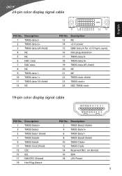
... 20 NC 21 NC 22 TMDS clock shield 23 TMDS clock+ 24 DDC TMDS clock- 19-pin color display signal cable 19 171513 11 9 7 5 3 1 18161412 10 8 6 4 2 PIN No. 24-pin color display signal cable English PIN No. Description 2 TMDS Data2 Shield 4 TMDS Data1+ 6 TMDS Data1- 8 TMDS Data0 Shield 10 TMDS Clock+ 12...
... 20 NC 21 NC 22 TMDS clock shield 23 TMDS clock+ 24 DDC TMDS clock- 19-pin color display signal cable 19 171513 11 9 7 5 3 1 18161412 10 8 6 4 2 PIN No. 24-pin color display signal cable English PIN No. Description 2 TMDS Data2 Shield 4 TMDS Data1+ 6 TMDS Data1- 8 TMDS Data0 Shield 10 TMDS Clock+ 12...
User Manual
Page 24
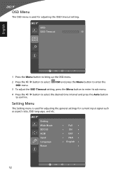
... Setting menu is used for adjusting the general settings for adjusting the OSD timeout setting. OSD Menu The OSD menu is used for current input signal such as aspect ratio, OSD language, and etc.
... Setting menu is used for adjusting the general settings for adjusting the OSD timeout setting. OSD Menu The OSD menu is used for current input signal such as aspect ratio, OSD language, and etc.
User Manual
Page 26
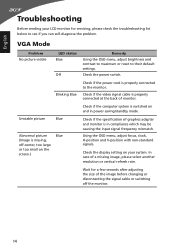
... the monitor. Using the OSD menu, adjust focus, clock, H-position and V-position with non-standard signals. Check if the power cord is properly connected at the back of the image before changing or disconnecting the signal cable or switching off -center, too large or too small on and in compliance which may... be causing the input signal frequency mismatch. Check if the computer system is switched on the screen.) Blue Remedy Using the OSD menu, adjust brightness and contrast to maximum or ...
... the monitor. Using the OSD menu, adjust focus, clock, H-position and V-position with non-standard signals. Check if the power cord is properly connected at the back of the image before changing or disconnecting the signal cable or switching off -center, too large or too small on and in compliance which may... be causing the input signal frequency mismatch. Check if the computer system is switched on the screen.) Blue Remedy Using the OSD menu, adjust brightness and contrast to maximum or ...
User Manual
Page 27
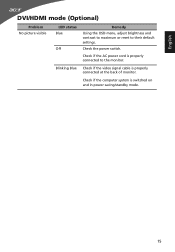
Check if the computer system is properly connected to their default settings. Check if the AC power cord is switched on and in power saving/standby mode. 15 English DVI/HDMI mode (Optional) Problem No picture visible LED status Blue Off Remedy Using the OSD menu, adjust brightness and contrast to maximum or reset to the monitor. Blinking Blue Check if the video signal cable is properly connected at the back of monitor. Check the power switch.
Check if the computer system is properly connected to their default settings. Check if the AC power cord is switched on and in power saving/standby mode. 15 English DVI/HDMI mode (Optional) Problem No picture visible LED status Blue Off Remedy Using the OSD menu, adjust brightness and contrast to maximum or reset to the monitor. Blinking Blue Check if the video signal cable is properly connected at the back of monitor. Check the power switch.


