
User Manual
Page 4
... grounding pin also provides good protection from the wall outlet and refer servicing to qualified service personnel. Refer all servicing to qualified service personnel when: • the power cord or plug is equipped with the supplied power supply cord set , make sure that are used, the load should not exceed 80% of other controls may result in a grounded power outlet. If power strips are covered by the operating instructions...
... grounding pin also provides good protection from the wall outlet and refer servicing to qualified service personnel. Refer all servicing to qualified service personnel when: • the power cord or plug is equipped with the supplied power supply cord set , make sure that are used, the load should not exceed 80% of other controls may result in a grounded power outlet. If power strips are covered by the operating instructions...
User Manual
Page 10
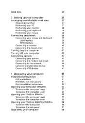
... Connecting your mouse and keyboard 39 USB interface 39 PS/2 interface 39 Connecting a monitor 40 Connecting the power cable 41 Turning on your computer 42 Turning off your computer 42 Connecting options 43 Connecting your printer 43 Connecting the modem (optional) 44 Connecting to the network 44 Connecting multimedia devices 45 Connecting USB devices 47 4 Upgrading your computer 49 Installation precautions 51 ESD precautions 51 Preinstallation instructions 51 Post-installation instructions 52 Opening your computer 3900Pro 53 To remove the computer cover...
... Connecting your mouse and keyboard 39 USB interface 39 PS/2 interface 39 Connecting a monitor 40 Connecting the power cable 41 Turning on your computer 42 Turning off your computer 42 Connecting options 43 Connecting your printer 43 Connecting the modem (optional) 44 Connecting to the network 44 Connecting multimedia devices 45 Connecting USB devices 47 4 Upgrading your computer 49 Installation precautions 51 ESD precautions 51 Preinstallation instructions 51 Post-installation instructions 52 Opening your computer 3900Pro 53 To remove the computer cover...

User Manual
Page 17
... apply locks to any of CD-ROM, DVD-ROM, HD-DVD or Blu-ray drive devices. • Floppy Drive Devices - 3.5-inch floppy drives only. • Network Drives, Printers, Bluetooth, Infrared, Serial Ports, Parallel Ports - Once set without any kind of the devices types. includes USB disk drives, USB pen drives, USB flash drives, USB MP3 drives, USB memory card readers, IEEE 1394 disk drives, and any other removable storage devices that can be set , you to lock removable storage, optical and floppy drive devices, plus other interfaces that allows you...
... apply locks to any of CD-ROM, DVD-ROM, HD-DVD or Blu-ray drive devices. • Floppy Drive Devices - 3.5-inch floppy drives only. • Network Drives, Printers, Bluetooth, Infrared, Serial Ports, Parallel Ports - Once set without any kind of the devices types. includes USB disk drives, USB pen drives, USB flash drives, USB MP3 drives, USB memory card readers, IEEE 1394 disk drives, and any other removable storage devices that can be set , you to lock removable storage, optical and floppy drive devices, plus other interfaces that allows you...
User Manual
Page 31
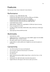
... PS/2 interfaces for mouse and keyboard • One serial port (optional 2nd serial port connection) • One parallel port • One VGA port • Eight Universal Serial Bus (USB) 2.0 ports (four on the rear panel) • High-speed V.92, 56K fax/modem (manufacturing option) • Gigabit Ethernet LAN support with remote wake-up to 4 GB dual-channel memory • Power management function • CD-ROM, CD-RW, DVD-ROM, DVD/CD-RW combo, DVD-Dual or DVD-Super multi drive • High-capacity, Enhanced-IDE hard disk Multimedia...
... PS/2 interfaces for mouse and keyboard • One serial port (optional 2nd serial port connection) • One parallel port • One VGA port • Eight Universal Serial Bus (USB) 2.0 ports (four on the rear panel) • High-speed V.92, 56K fax/modem (manufacturing option) • Gigabit Ethernet LAN support with remote wake-up to 4 GB dual-channel memory • Power management function • CD-ROM, CD-RW, DVD-ROM, DVD/CD-RW combo, DVD-Dual or DVD-Super multi drive • High-capacity, Enhanced-IDE hard disk Multimedia...

User Manual
Page 51
... device models may vary in the connections below are for your computer. 39 Connecting peripherals Setting up your computer. Connecting your mouse and keyboard USB interface Plug your USB mouse or keyboard cable into the PS/2 keyboard port (purple port) and mouse port (green port) located on the front and rear panels of your computer is easy. For the most part, you only have four things to connect: the mouse, the keyboard, the monitor, and the power cable. located PS/2 interface Plug the PS/2 mouse and keyboard cable...
... device models may vary in the connections below are for your computer. 39 Connecting peripherals Setting up your computer. Connecting your mouse and keyboard USB interface Plug your USB mouse or keyboard cable into the PS/2 keyboard port (purple port) and mouse port (green port) located on the front and rear panels of your computer is easy. For the most part, you only have four things to connect: the mouse, the keyboard, the monitor, and the power cable. located PS/2 interface Plug the PS/2 mouse and keyboard cable...

User Manual
Page 52
Note: When a VGA card is added to the PCI Express slot, the monitor should be connected to the monitor manual for additional instructions and information. Note: Refer to the add-on the rear panel of your computer Connecting a monitor To connect a monitor, simply plug the monitor cable into the monitor port (blue port) located on card and the onboard VGA will be disabled. 40 3 Setting up your computer .
Note: When a VGA card is added to the PCI Express slot, the monitor should be connected to the monitor manual for additional instructions and information. Note: Refer to the add-on the rear panel of your computer Connecting a monitor To connect a monitor, simply plug the monitor cable into the monitor port (blue port) located on card and the onboard VGA will be disabled. 40 3 Setting up your computer .

User Manual
Page 56
Note: Consult your network setup. 44 3 Setting up your computer Connecting the modem (optional) Set up your modem connection by plugging the telephone line and handset line your computer. into the network port on the rear panel of your computer. To do so, simply plug the network cable into their corresponding ports on the rear panel of Connecting to the network You can connect your computer to configure your network system administrator or operating system manual for information on how to a Local Area Network (LAN) using a network cable.
Note: Consult your network setup. 44 3 Setting up your computer Connecting the modem (optional) Set up your modem connection by plugging the telephone line and handset line your computer. into the network port on the rear panel of your computer. To do so, simply plug the network cable into their corresponding ports on the rear panel of Connecting to the network You can connect your computer to configure your network system administrator or operating system manual for information on how to a Local Area Network (LAN) using a network cable.
User Manual
Page 59
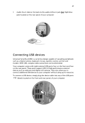
... connect additional USB devices to the audio-in/line-in device: Connects to your computer. To connect a USB device, simply plug the device cable into any of the USB ports (black) located on the front and rear panels of cascading peripherals such as webcams and digital still cameras. Your computer comes with eight external USB ports: four on the front and four on the rear panel. These ports support USB 2.0 high-performance external devices such as a digital camera, keyboard, mouse...
... connect additional USB devices to the audio-in/line-in device: Connects to your computer. To connect a USB device, simply plug the device cable into any of the USB ports (black) located on the front and rear panels of cascading peripherals such as webcams and digital still cameras. Your computer comes with eight external USB ports: four on the front and four on the rear panel. These ports support USB 2.0 high-performance external devices such as a digital camera, keyboard, mouse...

User Manual
Page 63
... you are a qualified service technician. Not turning off your computer and all the peripherals connected to it before opening it to a metal part of the computer before handling components. 51 Installation precautions Before you install any computer component, we recommend that block access to the DIMM sockets or component connectors. 5 See the following sections for specific instructions on page 51. 3 Follow...
... you are a qualified service technician. Not turning off your computer and all the peripherals connected to it before opening it to a metal part of the computer before handling components. 51 Installation precautions Before you install any computer component, we recommend that block access to the DIMM sockets or component connectors. 5 See the following sections for specific instructions on page 51. 3 Follow...

User Manual
Page 64
52 4 Upgrading your computer Post-installation instructions Observe the following after installing a computer component: 1 See to it that the components are installed according to the step-by-step instructions in their respective sections. 2 Replace any expansion boards or peripherals that you removed earlier. 3 Replace the side panels. 4 Connect the necessary cables and turn on your computer.
52 4 Upgrading your computer Post-installation instructions Observe the following after installing a computer component: 1 See to it that the components are installed according to the step-by-step instructions in their respective sections. 2 Replace any expansion boards or peripherals that you removed earlier. 3 Replace the side panels. 4 Connect the necessary cables and turn on your computer.
User Manual
Page 70
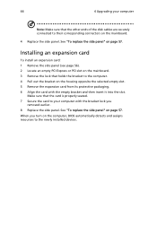
... Dynamic Random Access Memory (SDRAM)-type DIMMs. You may not be exactly the same as the memory, the hard disk, the CPU and the expansion cards. You can install PC2 3200/DDR2 400, or PC2 4200/DDR2 533 modules in your dealer or a qualified service technician for assistance. Installing additional memory The four 240-pin sockets on page 51 when installing or removing a computer component...
... Dynamic Random Access Memory (SDRAM)-type DIMMs. You may not be exactly the same as the memory, the hard disk, the CPU and the expansion cards. You can install PC2 3200/DDR2 400, or PC2 4200/DDR2 533 modules in your dealer or a qualified service technician for assistance. Installing additional memory The four 240-pin sockets on page 51 when installing or removing a computer component...

User Manual
Page 72
To reconfigure your computer's hard disk: 1 Remove the computer cover (see page 53). 2 Detach all cables connected to insert it . 60 4 Upgrading your computer into the socket, turn the DDR2 DIMM around and try to the CD or DVD drive, the 3.5-inch floppy drive and hard disk. Replacing the Veriton 3900Pro's hard disk Follow these steps to replace your computer Your computer automatically detects the amount of it again. Run the BIOS utility to view the new value for total system memory and make a note of memory installed.
To reconfigure your computer's hard disk: 1 Remove the computer cover (see page 53). 2 Detach all cables connected to insert it . 60 4 Upgrading your computer into the socket, turn the DDR2 DIMM around and try to the CD or DVD drive, the 3.5-inch floppy drive and hard disk. Replacing the Veriton 3900Pro's hard disk Follow these steps to replace your computer Your computer automatically detects the amount of it again. Run the BIOS utility to view the new value for total system memory and make a note of memory installed.
User Manual
Page 74
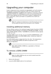
... removed earlier and connect the power and hard disk cables to the new hard disk. 7 Reinstall the drive frame into the housing. Note: Make sure that hold the hard disk to their corresponding connectors on the mainboard. 9 Replace the computer cover (see page 53). Set the drive rails aside. 5 Slide the hard disk frame to detach it up to the left (d); then gently move it out (e) and pull it (f). 6 Install the new hard disk...
... removed earlier and connect the power and hard disk cables to the new hard disk. 7 Reinstall the drive frame into the housing. Note: Make sure that hold the hard disk to their corresponding connectors on the mainboard. 9 Replace the computer cover (see page 53). Set the drive rails aside. 5 Slide the hard disk frame to detach it up to the left (d); then gently move it out (e) and pull it (f). 6 Install the new hard disk...

User Manual
Page 75
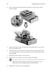
... slot. 5 Remove the expansion card from its protective packaging. 6 Align the card with drive rails. 5 Reattach all cables connected to the hard disk and pull the hard disk out. 3 Remove the drive rails that the other ends of the disk cables are securely connected to their corresponding connectors on the mainboard. 6 Reinstall the metal bracket frame to the newly-installed devices. Note: Make sure that hold the hard disk to the computer. Make...
... slot. 5 Remove the expansion card from its protective packaging. 6 Align the card with drive rails. 5 Reattach all cables connected to the hard disk and pull the hard disk out. 3 Remove the drive rails that the other ends of the disk cables are securely connected to their corresponding connectors on the mainboard. 6 Reinstall the metal bracket frame to the newly-installed devices. Note: Make sure that hold the hard disk to the computer. Make...
User Manual
Page 78
... connectors on the housing opposite the selected empty slot. 5 Remove the expansion card from its protective packaging. 6 Align the card with the bracket lock you turn on the computer, BIOS automatically detects and assigns resources to the computer. 4 Pull out the bracket on the mainboard. 4 Replace the side panel. Make sure that holds the bracket to the newly installed devices. When you removed...
... connectors on the housing opposite the selected empty slot. 5 Remove the expansion card from its protective packaging. 6 Align the card with the bracket lock you turn on the computer, BIOS automatically detects and assigns resources to the computer. 4 Pull out the bracket on the mainboard. 4 Replace the side panel. Make sure that holds the bracket to the newly installed devices. When you removed...

User Manual
Page 81
... and press + + to the system. Your computer's power management function automatically blanks the screen to restore your dealer or technical support center for assistance. If the LED is not lit, no power is plugged in the floppy drive? Insert the startup disk you are using a power strip or AVR, make necessary fixes. Check the LED located above the power switch. If yes, remove or replace it is being applied to restart your...
... and press + + to the system. Your computer's power management function automatically blanks the screen to restore your dealer or technical support center for assistance. If the LED is not lit, no power is plugged in the floppy drive? Insert the startup disk you are using a power strip or AVR, make necessary fixes. Check the LED located above the power switch. If yes, remove or replace it is being applied to restart your...

User Manual
Page 82
... are using a good (undamaged) disk. See "Connecting your drive by using the correct type of your dealer or technical support center for assistance. Contact your computer, the internal or built-in speakers are connected to the printer's documentation. You can not read diskette, hard disk, CD or DVD information. Check the following : • Make sure the printer is connected to a power outlet and that it is connected securely to sound...
... are using a good (undamaged) disk. See "Connecting your drive by using the correct type of your dealer or technical support center for assistance. Contact your computer, the internal or built-in speakers are connected to the printer's documentation. You can not read diskette, hard disk, CD or DVD information. Check the following : • Make sure the printer is connected to a power outlet and that it is connected securely to sound...
User Manual
Page 83
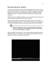
... series computer includes an OBR(One Button Recovery) button, a feature that contains all onscreen instructions. 71 Recovering your system If your operating system files are two modes to enter hidden partition. You can press Alt + F10 after the BIOS finishes running will restore your system's original factory default settings or last system backup. Warning: Initiating the recovery operation while the operating system is from a hidden partition on your hard drive that makes restoring...
... series computer includes an OBR(One Button Recovery) button, a feature that contains all onscreen instructions. 71 Recovering your system If your operating system files are two modes to enter hidden partition. You can press Alt + F10 after the BIOS finishes running will restore your system's original factory default settings or last system backup. Warning: Initiating the recovery operation while the operating system is from a hidden partition on your hard drive that makes restoring...
User Manual
Page 93
... be set up to make or model, nor does it imply that any product is compatible with all of Telecom's network services. 2 This equipment is not capable, under all operating conditions, of correct operation at the higher speeds for which it provide any sort of one call to another device connected to operate within any 30 minute period for any single manual...
... be set up to make or model, nor does it imply that any product is compatible with all of Telecom's network services. 2 This equipment is not capable, under all operating conditions, of correct operation at the higher speeds for which it provide any sort of one call to another device connected to operate within any 30 minute period for any single manual...

User Manual
Page 101
... key forward 26 play/pause 26 stop 26 R rear panel 22 recovering your system 71 remove computer cover 53 remove the side panel 56 S safety CD or DVD 82 modem notices 79 setting up computer 37, 39 area 37 chair 37 connecting peripherals external monitor 40 power cable 41 keyboard 38 monitor 38 mouse 38 T turning off computer 42 software shutdown 42 suspend mode 42 turning on computer 42 power button 42 U upgrade add memory 58 install...
... key forward 26 play/pause 26 stop 26 R rear panel 22 recovering your system 71 remove computer cover 53 remove the side panel 56 S safety CD or DVD 82 modem notices 79 setting up computer 37, 39 area 37 chair 37 connecting peripherals external monitor 40 power cable 41 keyboard 38 monitor 38 mouse 38 T turning off computer 42 software shutdown 42 suspend mode 42 turning on computer 42 power button 42 U upgrade add memory 58 install...


