Service Guide
Page 59
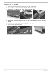
two one each side. 6. Disconnect the LCD cable then take out the antenna from the upper case. 4. Unscrew the four screws holding the LCD hinges; Then remove the entire LCD module. 52 Chapter 3 Remove the four screws that secures the middle cover; Disconnect the left wireless LAN antenna line. Then take out the cable from the upper case with the assistance of a plastic flat head screw driver. 3. Detach middle cover with a tweezers. 5. two on each side. 2. Removing the LCD Module 1.
two one each side. 6. Disconnect the LCD cable then take out the antenna from the upper case. 4. Unscrew the four screws holding the LCD hinges; Then remove the entire LCD module. 52 Chapter 3 Remove the four screws that secures the middle cover; Disconnect the left wireless LAN antenna line. Then take out the cable from the upper case with the assistance of a plastic flat head screw driver. 3. Detach middle cover with a tweezers. 5. two on each side. 2. Removing the LCD Module 1.


