CE DoC
Page 1
... for your body Radio Equipment Model: AX201D2W, Operation frequency and radio-frequency power are listed as below: [Bluetooth] 2402-2480MHz < 10 dBm [WLAN] 2412MHz-2462MHz < 20dBm, 5180-5320MHz < 23dBm, 5500-5700MHz < 23dBm Year to begin affixing CE marking:2021 RU Jan, Sr.Manager 2021-03-16 Note: Open the Start Menu and search for 'Acer Documents' for help with the...
... for your body Radio Equipment Model: AX201D2W, Operation frequency and radio-frequency power are listed as below: [Bluetooth] 2402-2480MHz < 10 dBm [WLAN] 2412MHz-2462MHz < 20dBm, 5180-5320MHz < 23dBm, 5500-5700MHz < 23dBm Year to begin affixing CE marking:2021 RU Jan, Sr.Manager 2021-03-16 Note: Open the Start Menu and search for 'Acer Documents' for help with the...
ErP Energy-related Product directive technical document
Page 1
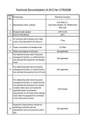
... with a display unit or light 4 source, the total content of mercury is Notebook computer Acer Italy s.r.l, Viale delle Industrie 1/A, 20020 Arese (MI), Italy CP713-3W 2021 0 mg 5 Power consumption of standby mode 6 Power consumption of off mode The default time after which the power management function, or similar function, 7 has switched the equipment into standby mode The default time after which the power 8 management function, or similar function, has switched the...
... with a display unit or light 4 source, the total content of mercury is Notebook computer Acer Italy s.r.l, Viale delle Industrie 1/A, 20020 Arese (MI), Italy CP713-3W 2021 0 mg 5 Power consumption of standby mode 6 Power consumption of off mode The default time after which the power management function, or similar function, 7 has switched the equipment into standby mode The default time after which the power 8 management function, or similar function, has switched the...
Lifecycle Extension Guide
Page 3
...: NOTE: For replacement parts, always use only Acer certified components in the chapter "Disassembly Procedures". Self-Repair 1-1 NOTE: NOTE: Do not attempt to safeguard quality, optimum system performance, stability and reliability of the product. Depending on model, the following key components are eligible for self-repair (if applicable); Battery pack HDD / SSD module DIMM module(s) ...
...: NOTE: For replacement parts, always use only Acer certified components in the chapter "Disassembly Procedures". Self-Repair 1-1 NOTE: NOTE: Do not attempt to safeguard quality, optimum system performance, stability and reliability of the product. Depending on model, the following key components are eligible for self-repair (if applicable); Battery pack HDD / SSD module DIMM module(s) ...
Lifecycle Extension Guide
Page 4
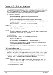
... system BIOS and Drivers for this product. To update the system BIOS: Download the desired system BIOS version from Acer: Select the Start button Go to create a Factory Default recovery media. Press Download to start automatically once the download is completed Software Recovery 0 This product has embedded software recovery tools which is available in order to the chapter "Recovery" which can be listed on the screen. NOTE: NOTE: System BIOS upgrades...
... system BIOS and Drivers for this product. To update the system BIOS: Download the desired system BIOS version from Acer: Select the Start button Go to create a Factory Default recovery media. Press Download to start automatically once the download is completed Software Recovery 0 This product has embedded software recovery tools which is available in order to the chapter "Recovery" which can be listed on the screen. NOTE: NOTE: System BIOS upgrades...
Lifecycle Extension Guide
Page 5
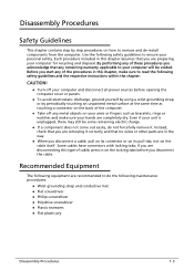
... all power sources before you disconnect a cable, pull on its connector or on its pull-tab, not on the cable itself. Each procedure included in on the locking tabs before opening the computer cover or panels. To avoid electrostatic discharge, ground yourself by using a wrist grounding strap or by step procedures on how to remove and de-install...
... all power sources before you disconnect a cable, pull on its connector or on its pull-tab, not on the cable itself. Each procedure included in on the locking tabs before opening the computer cover or panels. To avoid electrostatic discharge, ground yourself by using a wrist grounding strap or by step procedures on how to remove and de-install...

Lifecycle Extension Guide
Page 7
Pre-disassembly Instructions 0 Do the following prior to starting any maintenance procedures: 1. Remove the power adapter from the microSD card slot (C) (Figure 1-2). Remove the microSD card from the USB Type-C port (A or B) as shown in Figure 1-1. 3. C Figure 1-2. AC Adapter Outlet 4. Disassembly Procedures 1-5 Place the system on a stable work surface. 2. AB Figure 1-1. MicroSD Card Removal NOTE: NOTE: Make sure the system is completely powered off. Remove all cables from system.
Pre-disassembly Instructions 0 Do the following prior to starting any maintenance procedures: 1. Remove the power adapter from the microSD card slot (C) (Figure 1-2). Remove the microSD card from the USB Type-C port (A or B) as shown in Figure 1-1. 3. C Figure 1-2. AC Adapter Outlet 4. Disassembly Procedures 1-5 Place the system on a stable work surface. 2. AB Figure 1-1. MicroSD Card Removal NOTE: NOTE: Make sure the system is completely powered off. Remove all cables from system.

Lifecycle Extension Guide
Page 14
D D D F WEEE Annex VII Component: Touchpad Module E E Figure 1-13. Touchpad Module Removal 1-12 Disassembly Procedures Using the screwdriver, push the guide pins (D) firmly to disengage it from the bottom latches (E), and then remove the touchpad module (F) from the top assembly (Figure 1-13). 6. With one hand is placed underneath the touchpad module, push the touchpad module slightly to release them from the top assembly (Figure 1-13). 5.
D D D F WEEE Annex VII Component: Touchpad Module E E Figure 1-13. Touchpad Module Removal 1-12 Disassembly Procedures Using the screwdriver, push the guide pins (D) firmly to disengage it from the bottom latches (E), and then remove the touchpad module (F) from the top assembly (Figure 1-13). 6. With one hand is placed underneath the touchpad module, push the touchpad module slightly to release them from the top assembly (Figure 1-13). 5.

Lifecycle Extension Guide
Page 16
SSD Module Removal 1-14 Disassembly Procedures WEEE Annex VII Component: SSD Module C D Figure 1-16. 3. Remove the SSD module (C) from the mainboard connector (D) (Figure 1-16).
SSD Module Removal 1-14 Disassembly Procedures WEEE Annex VII Component: SSD Module C D Figure 1-16. 3. Remove the SSD module (C) from the mainboard connector (D) (Figure 1-16).

Lifecycle Extension Guide
Page 19
Figure 1-21. LCD Module Removal Disassembly Procedures 1-17 Figure 1-22. 6. Then remove the LCD module away from the top assembly (Figure 1-22). Open the top assembly again. LCD Module Removal 7. Close the top assembly and lift both LCD hinges until they are fully extended (Figure 1-21).
Figure 1-21. LCD Module Removal Disassembly Procedures 1-17 Figure 1-22. 6. Then remove the LCD module away from the top assembly (Figure 1-22). Open the top assembly again. LCD Module Removal 7. Close the top assembly and lift both LCD hinges until they are fully extended (Figure 1-21).

Lifecycle Extension Guide
Page 30
In the event that the LCD Module, WLAN Antenna, Fingerprint Module, USB Board, and Mainboard have been disassembled prior removing the top assembly. NOTE: NOTE: The keyboard is included as part of the top assembly and cannot be used, replace the entire top assembly. Figure 1-40. Top Assembly Removal (Keyboard Removal) 0 Prerequisite: Ensure that the keyboard can no longer be disassembled. Top Assembly (Keyboard) 1-28 Disassembly Procedures
In the event that the LCD Module, WLAN Antenna, Fingerprint Module, USB Board, and Mainboard have been disassembled prior removing the top assembly. NOTE: NOTE: The keyboard is included as part of the top assembly and cannot be used, replace the entire top assembly. Figure 1-40. Top Assembly Removal (Keyboard Removal) 0 Prerequisite: Ensure that the keyboard can no longer be disassembled. Top Assembly (Keyboard) 1-28 Disassembly Procedures
Lifecycle Extension Guide
Page 31
... the corrective action. CMOS checksum error Contact your dealer or an authorized service center. Equipment configuration error Press F2 (during POST) to enter BIOS utility, then press Exit in the BIOS utility to open the computer yourself; Hard disk 0 extended type error Contact your dealer or an authorized service center. Memory size mismatch Press F2 (during POST) to enter BIOS utility, then press Exit in the BIOS utility to reboot. Troubleshooting tips 0 This computer...
... the corrective action. CMOS checksum error Contact your dealer or an authorized service center. Equipment configuration error Press F2 (during POST) to enter BIOS utility, then press Exit in the BIOS utility to open the computer yourself; Hard disk 0 extended type error Contact your dealer or an authorized service center. Memory size mismatch Press F2 (during POST) to enter BIOS utility, then press Exit in the BIOS utility to reboot. Troubleshooting tips 0 This computer...

Lifecycle Extension Guide
Page 37
... in screen, then press and hold down the Shift key while you select the Power icon > Restart to restart your computer restarts, select Troubleshoot > Reset this PC, select Get started. After your computer into Recovery Mode. Under Option 2: Restart your personal data 0 There are three options to choose from: Option 1: Select Start > Settings > Update & Security Reset this PC. Personal Data Removal Removing your...
... in screen, then press and hold down the Shift key while you select the Power icon > Restart to restart your computer restarts, select Troubleshoot > Reset this PC, select Get started. After your computer into Recovery Mode. Under Option 2: Restart your personal data 0 There are three options to choose from: Option 1: Select Start > Settings > Update & Security Reset this PC. Personal Data Removal Removing your...

User Manual
Page 2
... are for technical or editorial errors or omissions contained in this manual. Model number Serial number Date of purchase Place of purchase Google and Google Play are trademarks or registered trademarks of Google LLC. Acer Chromebook Spin 713 / Acer Chromebook Enterprise Spin 713 Covers: CP713-3W This revision: March 2021 Important This manual contains proprietary information that do not apply to www.acer.com/register-product, and...
... are for technical or editorial errors or omissions contained in this manual. Model number Serial number Date of purchase Place of purchase Google and Google Play are trademarks or registered trademarks of Google LLC. Acer Chromebook Spin 713 / Acer Chromebook Enterprise Spin 713 Covers: CP713-3W This revision: March 2021 Important This manual contains proprietary information that do not apply to www.acer.com/register-product, and...
User Manual
Page 3
... Table of contents - 3 Getting started 4 Turn on your Chromebook 4 Select your language settings 4 Connect to a network 4 Accept the Terms of Service 4 First-time sign-in 4 Create a new Google Account 4 Browse as a guest 4 Enterprise enrollment (optional 5 Sign in to your Google Account 5 Your Acer Chromebook tour 6 Front view 6 Keyboard view 7 Function keys 8 Common keyboard shortcuts 8 Touchpad 9 Left view 10 USB Type-C information 10 Right view 11 USB 3.2 Gen 1 information 11 Rear...
... Table of contents - 3 Getting started 4 Turn on your Chromebook 4 Select your language settings 4 Connect to a network 4 Accept the Terms of Service 4 First-time sign-in 4 Create a new Google Account 4 Browse as a guest 4 Enterprise enrollment (optional 5 Sign in to your Google Account 5 Your Acer Chromebook tour 6 Front view 6 Keyboard view 7 Function keys 8 Common keyboard shortcuts 8 Touchpad 9 Left view 10 USB Type-C information 10 Right view 11 USB 3.2 Gen 1 information 11 Rear...
User Manual
Page 4
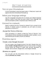
... started GETTING STARTED Turn on your default language setting. Accept the Terms of Service Once connected to the Internet. Connect to a network Select a network from the "Connect to network" list to connect to a network, accept the Terms of Service. Your Chromebook will appear when the Chromebook first boots up a new account. A "Welcome" screen will then download any available system updates, so you may be prompted to type in Create a new Google Account You can also use the Chromebook without...
... started GETTING STARTED Turn on your default language setting. Accept the Terms of Service Once connected to the Internet. Connect to a network Select a network from the "Connect to network" list to connect to a network, accept the Terms of Service. Your Chromebook will appear when the Chromebook first boots up a new account. A "Welcome" screen will then download any available system updates, so you may be prompted to type in Create a new Google Account You can also use the Chromebook without...
User Manual
Page 6
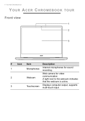
A light next to the webcam indicates that the webcam is active. 3 Touchscreen Displays computer output, supports multi-touch input. Web camera for sound recording. Your Acer Chromebook tour YOUR ACER CHROMEBOOK TOUR Front view 1 2 3 # Icon Item Description 1 Microphones Internal microphones for video 2 Webcam communication. 6 -
A light next to the webcam indicates that the webcam is active. 3 Touchscreen Displays computer output, supports multi-touch input. Web camera for sound recording. Your Acer Chromebook tour YOUR ACER CHROMEBOOK TOUR Front view 1 2 3 # Icon Item Description 1 Microphones Internal microphones for video 2 Webcam communication. 6 -
User Manual
Page 8
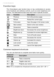
...Brightness down Decreases the volume. Note: For a complete list of keyboard shortcuts, press Ctrl + Alt + / Your Acer Chromebook tour Function keys The Chromebook uses function keys or key combinations to complete some hardware and software controls, such as screen brightness and volume. Next window Switch to the previous page. Brightness up Increases the volume. Launcher Launch the Apps panel. Alt + Projects your screen. The dedicated function keys each have a specific function. Full-screen Open the page in full-screen mode. Alt + Toggles caps lock...
...Brightness down Decreases the volume. Note: For a complete list of keyboard shortcuts, press Ctrl + Alt + / Your Acer Chromebook tour Function keys The Chromebook uses function keys or key combinations to complete some hardware and software controls, such as screen brightness and volume. Next window Switch to the previous page. Brightness up Increases the volume. Launcher Launch the Apps panel. Alt + Projects your screen. The dedicated function keys each have a specific function. Full-screen Open the page in full-screen mode. Alt + Toggles caps lock...
User Manual
Page 10
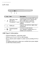
...; 4 and displays. 2 HDMI port Supports high-definition digital video connections. 3 Headset/speaker jack Connects to audio devices (e.g., speakers, headphones), or a headset with a USB Type-C connector. For optimal performance, please use a certified Acer power adapter or USB Power Delivery device. Your Acer Chromebook tour Left view 1 23 # Icon Item Description Connects to the provided USB Type-C USB Type-C port power adapter and to 3 A at 5~20 V. USB Type-C information • Supports DisplayPort™ audio/video output. • Delivers up to USB devices 1 with...
...; 4 and displays. 2 HDMI port Supports high-definition digital video connections. 3 Headset/speaker jack Connects to audio devices (e.g., speakers, headphones), or a headset with a USB Type-C connector. For optimal performance, please use a certified Acer power adapter or USB Power Delivery device. Your Acer Chromebook tour Left view 1 23 # Icon Item Description Connects to the provided USB Type-C USB Type-C port power adapter and to 3 A at 5~20 V. USB Type-C information • Supports DisplayPort™ audio/video output. • Delivers up to USB devices 1 with...
User Manual
Page 11
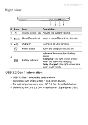
Power button Turns the computer on and off. Fully charged: The light shows blue when in AC mode. Right view Your Acer Chromebook tour - 11 # Icon 1 +/- 1 2 34 Item Description Volume control key Adjusts the system volume. 2 MicroSD card slot Insert a microSD card into this slot. 3 USB port Connects to USB devices. Indicates the computer's battery 4 Battery indicator status. Charging: The light shows amber when the battery is charging. USB 3.2 Gen 1 information • USB 3.2 Gen 1 compatible ports are blue. • Compatible with USB 3.2 Gen 1 and earlier...
Power button Turns the computer on and off. Fully charged: The light shows blue when in AC mode. Right view Your Acer Chromebook tour - 11 # Icon 1 +/- 1 2 34 Item Description Volume control key Adjusts the system volume. 2 MicroSD card slot Insert a microSD card into this slot. 3 USB port Connects to USB devices. Indicates the computer's battery 4 Battery indicator status. Charging: The light shows amber when the battery is charging. USB 3.2 Gen 1 information • USB 3.2 Gen 1 compatible ports are blue. • Compatible with USB 3.2 Gen 1 and earlier...
User Manual
Page 14
... of traditional software applications. files? most external storage devices (e.g.: USB thumb drives, removable hard drives). Why does my Chromebook need my Google Account information? Where can download the apps from the Google Play Store or use Microsoft Office software? It is the same account you into apps and services. How do I use them on the web. *Additional functionality available with a Microsoft 365 subscription. Your Chromebook uses your local...
... of traditional software applications. files? most external storage devices (e.g.: USB thumb drives, removable hard drives). Why does my Chromebook need my Google Account information? Where can download the apps from the Google Play Store or use Microsoft Office software? It is the same account you into apps and services. How do I use them on the web. *Additional functionality available with a Microsoft 365 subscription. Your Chromebook uses your local...


