

Aspire easyStore H340 Home Server Service Guide
Page 18
...is completed, you need to restart the server. Connect a USB keyboard to the debug board. 9. Locate the JP3 Debug/User mode jumper on page 27. 3. Connect a monitor to the debug board. 8. Connect the debug board cable to the rear panel. 7. Close the jumper to move between selections on the menu... bar. 10 Chapter 2 Turn on the mainboard. 4. The Setup Main menu will need a debug board. 1. Use the left and right arrow...
...is completed, you need to restart the server. Connect a USB keyboard to the debug board. 9. Locate the JP3 Debug/User mode jumper on page 27. 3. Connect a monitor to the debug board. 8. Connect the debug board cable to the rear panel. 7. Close the jumper to move between selections on the menu... bar. 10 Chapter 2 Turn on the mainboard. 4. The Setup Main menu will need a debug board. 1. Use the left and right arrow...
Aspire easyStore H340 Home Server Service Guide
Page 58
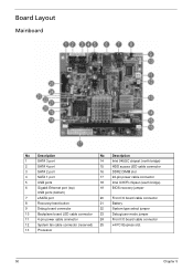
... BIOS recovery jumper 7 eSATA port 20 Front I/O board cable connector 8 Recovery/reset button 21 Battery 9 Debug board connector 22 System type select jumper 10 Backplane board LED cable connector 23 Debug/user mode jumper 11 4-pin power cable connector 24 Front I/O board cable connector 12 System fan cable connector (reserved) 25 x4 PCI Express slot. 13 Processor...
... BIOS recovery jumper 7 eSATA port 20 Front I/O board cable connector 8 Recovery/reset button 21 Battery 9 Debug board connector 22 System type select jumper 10 Backplane board LED cable connector 23 Debug/user mode jumper 11 4-pin power cable connector 24 Front I/O board cable connector 12 System fan cable connector (reserved) 25 x4 PCI Express slot. 13 Processor...

Service Guide
Page 18
... mode jumper on the monitor. 11. Connect the power cable to move between selections on the menu bar. 10 Chapter 2 Turn on the mainboard. 5. The Setup Main menu will need a debug board. 1. Use the left and right arrow keys to the rear panel. 7. See "Removing the System Cover" ... you fail to press F2 before POST is completed, you need to restart the server. Connect the debug board cable to the debug board. 8. Restart the system. 10. Connect a USB keyboard to the debug board connector on page 27. 3. During POST, press F2. Entering BIOS setup IMPORTANT:To enter the...
... mode jumper on the monitor. 11. Connect the power cable to move between selections on the menu bar. 10 Chapter 2 Turn on the mainboard. 5. The Setup Main menu will need a debug board. 1. Use the left and right arrow keys to the rear panel. 7. See "Removing the System Cover" ... you fail to press F2 before POST is completed, you need to restart the server. Connect the debug board cable to the debug board. 8. Restart the system. 10. Connect a USB keyboard to the debug board connector on page 27. 3. During POST, press F2. Entering BIOS setup IMPORTANT:To enter the...

Service Guide
Page 58
... BIOS recovery jumper 7 eSATA port 20 Front I/O board cable connector 8 Recovery/reset button 21 Battery 9 Debug board connector 22 System type select jumper 10 Backplane board LED cable connector 23 Debug/user mode jumper 11 4-pin power cable connector 24 Front I/O board cable connector 12 System fan cable connector (reserved) 25 x4 PCI Express slot. 13 Processor...
... BIOS recovery jumper 7 eSATA port 20 Front I/O board cable connector 8 Recovery/reset button 21 Battery 9 Debug board connector 22 System type select jumper 10 Backplane board LED cable connector 23 Debug/user mode jumper 11 4-pin power cable connector 24 Front I/O board cable connector 12 System fan cable connector (reserved) 25 x4 PCI Express slot. 13 Processor...


