Acer Aspire Z5770 and Z5771 Desktop Service Guide
Page 13
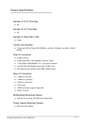
... Bay 0 N/A Number of Total Add-in Slot 0 3 slots Control and Indicator 0 1 dual color LED for Power LED (S0(Blue, not blink), S3(amber, not blink) , S4(off), S5(off)) Side I /O Connector 0 1 HDMI-in... (support Giga LAN) 1SPDIF Connector Motherboard Mounting Feature 0 Features for mounting 190*230mm2 motherboard Power Supply Mounting Feature 0 External power adapter Hardware Specifications and Configurations 1-7 ring color: black) 1 Card Reader (MS/SD/MMC 3 in and...
... Bay 0 N/A Number of Total Add-in Slot 0 3 slots Control and Indicator 0 1 dual color LED for Power LED (S0(Blue, not blink), S3(amber, not blink) , S4(off), S5(off)) Side I /O Connector 0 1 HDMI-in... (support Giga LAN) 1SPDIF Connector Motherboard Mounting Feature 0 Features for mounting 190*230mm2 motherboard Power Supply Mounting Feature 0 External power adapter Hardware Specifications and Configurations 1-7 ring color: black) 1 Card Reader (MS/SD/MMC 3 in and...

Acer Aspire Z5770 and Z5771 Desktop Service Guide
Page 14
Power Supply Electrical Design Feature 0 135W/180W in stable mode (Acer Assign System Power Unit) EPS 2.0 (The maximum no-load power consumption for EPS 2.0 is 0.5W or less for adapters with an output power of 50W to contact with MB shielding. Gasket on RJ45 has to 250W) ... mode: 35 dBA or under (under Windows OS) Idle mode: 28 dBA or under (under Windows OS), please refer to Acer test summary for MB (includes VGA card), touch panel control board. Apply aluminum foil between USB connector and MB shielding.
Power Supply Electrical Design Feature 0 135W/180W in stable mode (Acer Assign System Power Unit) EPS 2.0 (The maximum no-load power consumption for EPS 2.0 is 0.5W or less for adapters with an output power of 50W to contact with MB shielding. Gasket on RJ45 has to 250W) ... mode: 35 dBA or under (under Windows OS) Idle mode: 28 dBA or under (under Windows OS), please refer to Acer test summary for MB (includes VGA card), touch panel control board. Apply aluminum foil between USB connector and MB shielding.

Acer Aspire Z5770 and Z5771 Desktop Service Guide
Page 20
...3.0 connectors. (BOM option) On-board connectors 1 ILM+SKT+BP for LGA 1155 CPU (assign by Acer) 1 9Pin LCD Panel Power Supply Connector 2 SO-DDR3 memory sockets 1 90 Degree PCI-E x16 2.0 Slot (Support low-profile Graphic Cards, ...2.0 header for touch function control board connection 1 8pin USB 2.0 header for webcam module connection 1 10Pin Front Panel (Power SW+LED) 1 Jumper for clear CMOS 1 20pin header for DVI signal-in form VGA card. (BOM option) &#...
...3.0 connectors. (BOM option) On-board connectors 1 ILM+SKT+BP for LGA 1155 CPU (assign by Acer) 1 9Pin LCD Panel Power Supply Connector 2 SO-DDR3 memory sockets 1 90 Degree PCI-E x16 2.0 Slot (Support low-profile Graphic Cards, ...2.0 header for touch function control board connection 1 8pin USB 2.0 header for webcam module connection 1 10Pin Front Panel (Power SW+LED) 1 Jumper for clear CMOS 1 20pin header for DVI signal-in form VGA card. (BOM option) &#...

Acer Aspire Z5770 and Z5771 Desktop Service Guide
Page 193
... LED LCD CMI 21.5'W FHD None Glare Acer PN LK.2150D.005 Converter board setting LED LCD CMI 21.5'W FHD None Glare LK.2150D.006 LED LCD LPL 21.5''W FHD None Glare LM215WF4 ... TLD1 LF 250nit 5ms LK.23008.019 Troubleshooting 4-19 Below is the mapping table of converter board, so the converter board can provide the proper power to the panel. Converter board setup 0 For different panels need different power supply, so it needs to adjust the settings of LCD panel & coverter board setting: Table 4-4.
... LED LCD CMI 21.5'W FHD None Glare Acer PN LK.2150D.005 Converter board setting LED LCD CMI 21.5'W FHD None Glare LK.2150D.006 LED LCD LPL 21.5''W FHD None Glare LM215WF4 ... TLD1 LF 250nit 5ms LK.23008.019 Troubleshooting 4-19 Below is the mapping table of converter board, so the converter board can provide the proper power to the panel. Converter board setup 0 For different panels need different power supply, so it needs to adjust the settings of LCD panel & coverter board setting: Table 4-4.


