Service Guide
Page 7
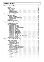
... the Memory Modules 40 Removing the TV Tuner Card 41 Removing the VGA Card 42 Removing the Front I/O and Card Reader Boards 44 Removing the Mainboard 47 Hardware Diagnostic Procedure 49 Chapter 4 System Troubleshooting 49 System Check Procedures 50 Power System Check 50 System External Inspection 50 System Internal Inspection 50...
... the Memory Modules 40 Removing the TV Tuner Card 41 Removing the VGA Card 42 Removing the Front I/O and Card Reader Boards 44 Removing the Mainboard 47 Hardware Diagnostic Procedure 49 Chapter 4 System Troubleshooting 49 System Check Procedures 50 Power System Check 50 System External Inspection 50 System Internal Inspection 50...

Service Guide
Page 15
Component 1 HDD drive 2 Optical drive 3 Expansion cards 4 Mainboard 5 Heat sink fan assembly 6 Power supply Chapter 1 7 Internal Components No.
Component 1 HDD drive 2 Optical drive 3 Expansion cards 4 Mainboard 5 Heat sink fan assembly 6 Power supply Chapter 1 7 Internal Components No.
Service Guide
Page 27
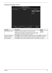
... you are overclocking. Frequency/Voltage Control Parameter Spread Spectrum Clock Processor Configuration DRAM Configuration Bus Configuration Description Option Enables or disables the reduction of the mainboard's EMI.
... you are overclocking. Frequency/Voltage Control Parameter Spread Spectrum Clock Processor Configuration DRAM Configuration Bus Configuration Description Option Enables or disables the reduction of the mainboard's EMI.

Service Guide
Page 37
Main Unit Disassembly MAIN UNIT DISASSEMBLY MAIN UNIT Ax2 SIDE PANEL FRONT BEZEL HEAT SINK FAN ASSEMBLY Bx2 OPTICAL DRIVE CPU Bx2 HDD-ODD BRACKET Ax3, Dx1 POWER SUPPLY Cx4 HDD MODULE HDD MEMORY MODULES Ax1 TV TUNER CARD Ax1 VGA CARD Dx1 FRONT I/O AND CARD READER BOARD BRACKET Dx6 MAINBOARD Dx2 FRONT I/O BOARD Dx2 CARD READER BOARD Screw List A B C D Screw #6-32 L5 BZN M3xL5 BZN #6-32*3/16 NI #6-32 L6 NI Part No. 86.00J07.B60 86.1A324.5R0 86.5A5B6.012 86.00J44.C60 Chapter 3 29
Main Unit Disassembly MAIN UNIT DISASSEMBLY MAIN UNIT Ax2 SIDE PANEL FRONT BEZEL HEAT SINK FAN ASSEMBLY Bx2 OPTICAL DRIVE CPU Bx2 HDD-ODD BRACKET Ax3, Dx1 POWER SUPPLY Cx4 HDD MODULE HDD MEMORY MODULES Ax1 TV TUNER CARD Ax1 VGA CARD Dx1 FRONT I/O AND CARD READER BOARD BRACKET Dx6 MAINBOARD Dx2 FRONT I/O BOARD Dx2 CARD READER BOARD Screw List A B C D Screw #6-32 L5 BZN M3xL5 BZN #6-32*3/16 NI #6-32 L6 NI Part No. 86.00J07.B60 86.1A324.5R0 86.5A5B6.012 86.00J44.C60 Chapter 3 29
Service Guide
Page 40
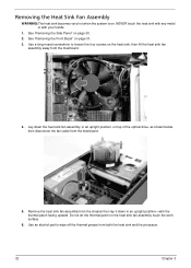
See "Removing the Front Bezel" on . Remove the heat sink fan assembly from the mainboard. 4. Use an alcohol pad to loosen the four screws on page 30. 2. Removing the Heat Sink Fan Assembly WARNING:The heat sink becomes very hot ... down the heat sink fan assembly, in an upright position-with your hands. 1. Use a long-nosed screwdriver to wipe off the thermal grease from the mainboard. 5. Lay down in an upright position, on the heat sink fan assembly touch the work surface. 6. Do not let the thermal patch on top of...
See "Removing the Front Bezel" on . Remove the heat sink fan assembly from the mainboard. 4. Use an alcohol pad to loosen the four screws on page 30. 2. Removing the Heat Sink Fan Assembly WARNING:The heat sink becomes very hot ... down the heat sink fan assembly, in an upright position-with your hands. 1. Use a long-nosed screwdriver to wipe off the thermal grease from the mainboard. 5. Lay down in an upright position, on the heat sink fan assembly touch the work surface. 6. Do not let the thermal patch on top of...
Service Guide
Page 41
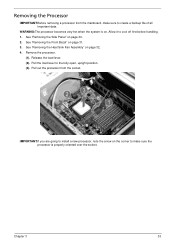
... page 32. 4. Remove the processor. (1). Release the load lever. (2). Removing the Processor IMPORTANT:Before removing a processor from the socket. Pull out the processor from the mainboard, make sure to make sure the processor is on page 30. 2. See "Removing the Heat Sink Fan Assembly" on page 31. 3. Pull the load lever...
... page 32. 4. Remove the processor. (1). Release the load lever. (2). Removing the Processor IMPORTANT:Before removing a processor from the socket. Pull out the processor from the mainboard, make sure to make sure the processor is on page 30. 2. See "Removing the Heat Sink Fan Assembly" on page 31. 3. Pull the load lever...
Service Guide
Page 46
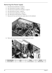
..." on page 33. 5. Removing the Power Supply 1. See "Removing the Processor" on page 34. 6. Disconnect the 4-pin and 24-pin power supply cables from the mainboard. 8.
..." on page 33. 5. Removing the Power Supply 1. See "Removing the Processor" on page 34. 6. Disconnect the 4-pin and 24-pin power supply cables from the mainboard. 8.

Service Guide
Page 49
See "Removing the Front Bezel" on page 37. 7. Screw (Quantity) #6-32 L5 BZN (3) Color Black Torque 5.5 to remove it from the mainboard. Gently pull the card to 6.5 kgf-cm 8. See "Removing the Hard Disk Drive" on page 31. 3. See "Removing the Processor" on page 30. 2. See "Removing the Side Panel" on page 33. 5. See "Removing the Heat Sink Fan Assembly" on page 34. 6. Remove the screw (A) that secures the card to the chassis. Removing the TV Tuner Card 1. See "Removing the Optical Drive" on page 32. 4. Part No. 86.00J07.B60 Chapter 3 41
See "Removing the Front Bezel" on page 37. 7. Screw (Quantity) #6-32 L5 BZN (3) Color Black Torque 5.5 to remove it from the mainboard. Gently pull the card to 6.5 kgf-cm 8. See "Removing the Hard Disk Drive" on page 31. 3. See "Removing the Processor" on page 30. 2. See "Removing the Side Panel" on page 33. 5. See "Removing the Heat Sink Fan Assembly" on page 34. 6. Remove the screw (A) that secures the card to the chassis. Removing the TV Tuner Card 1. See "Removing the Optical Drive" on page 32. 4. Part No. 86.00J07.B60 Chapter 3 41
Service Guide
Page 50
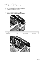
See "Removing the Processor" on page 31. 3. Screw (Quantity) #6-32 L5 BZN (3) Color Black Torque 5.5 to remove it from the mainboard. Gently pull the card to 6.5 kgf-cm 8. See "Removing the Front Bezel" on page 33. 5. Part No. 86.00J07.B60 42 Chapter 3 Remove the screw (A) that secures the card to the chassis. See "Removing the Side Panel" on page 32. 4. See "Removing the Heat Sink Fan Assembly" on page 30. 2. See "Removing the Hard Disk Drive" on page 34. 6. See "Removing the Optical Drive" on page 37. 7. Removing the VGA Card 1.
See "Removing the Processor" on page 31. 3. Screw (Quantity) #6-32 L5 BZN (3) Color Black Torque 5.5 to remove it from the mainboard. Gently pull the card to 6.5 kgf-cm 8. See "Removing the Front Bezel" on page 33. 5. Part No. 86.00J07.B60 42 Chapter 3 Remove the screw (A) that secures the card to the chassis. See "Removing the Side Panel" on page 32. 4. See "Removing the Heat Sink Fan Assembly" on page 30. 2. See "Removing the Hard Disk Drive" on page 34. 6. See "Removing the Optical Drive" on page 37. 7. Removing the VGA Card 1.

Service Guide
Page 51
Disconnect the VGA card cable from the mainboard. 9. Chapter 3 43
Disconnect the VGA card cable from the mainboard. 9. Chapter 3 43
Service Guide
Page 52
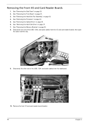
Disconnect the other end of the USB, 1394, and audio cables from the mainboard. 10. See "Removing the Side Panel" on page 34. 6. See "Removing the Optical Drive" on page 30. 2. See "Removing the Front Bezel" on page 37. 7. ...
Disconnect the other end of the USB, 1394, and audio cables from the mainboard. 10. See "Removing the Side Panel" on page 34. 6. See "Removing the Optical Drive" on page 30. 2. See "Removing the Front Bezel" on page 37. 7. ...

Service Guide
Page 55
... Screw (Quantity) #6-32 L6 NI (6) Chapter 3 Color Silver Torque 5.7 to the chassis. Removing the Mainboard 1. See "Removing the VGA Card" on page 41. 10. Remove the six screws (D) that secure the mainboard to 6.3 kgf-cm Part No. 86.00J44.C60 47 See "Removing the TV Tuner Card" on page... See "Removing the Hard Disk Drive" on page 33. 5. See "Removing the Processor" on page 37. 7. Disconnect the LED and SATA cable from the mainboard. 12. See "Removing the Heat Sink Fan Assembly" on page 31. 3. See "Removing the Front Bezel" on page 32. 4. See "Removing the Optical...
... Screw (Quantity) #6-32 L6 NI (6) Chapter 3 Color Silver Torque 5.7 to the chassis. Removing the Mainboard 1. See "Removing the VGA Card" on page 41. 10. Remove the six screws (D) that secure the mainboard to 6.3 kgf-cm Part No. 86.00J44.C60 47 See "Removing the TV Tuner Card" on page... See "Removing the Hard Disk Drive" on page 33. 5. See "Removing the Processor" on page 37. 7. Disconnect the LED and SATA cable from the mainboard. 12. See "Removing the Heat Sink Fan Assembly" on page 31. 3. See "Removing the Front Bezel" on page 32. 4. See "Removing the Optical...

Service Guide
Page 74
Board Layout Mainboard No 1 2 3 4 5 6 7 8 9 10 11 12 13 14 66 Code LEDH1 N/A USBF3 USBF2 USBF1 PCIEX1 PCIE1 AUDIOF1 N/A N/A PWR1 U17 DIMM1-2 DIMM3-4 Description Power and switch LED cable connector Not available at this model Front USB connector Front USB connector Front USB connector PCI Express x16 slot PCI Express x1 slot Front audio connector Not available at this model Not available at this model 4-pin ATX power connector Processor socket DIMM slot DIMM slot Chapter 5
Board Layout Mainboard No 1 2 3 4 5 6 7 8 9 10 11 12 13 14 66 Code LEDH1 N/A USBF3 USBF2 USBF1 PCIEX1 PCIE1 AUDIOF1 N/A N/A PWR1 U17 DIMM1-2 DIMM3-4 Description Power and switch LED cable connector Not available at this model Front USB connector Front USB connector Front USB connector PCI Express x16 slot PCI Express x1 slot Front audio connector Not available at this model Not available at this model 4-pin ATX power connector Processor socket DIMM slot DIMM slot Chapter 5

