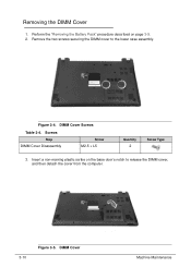
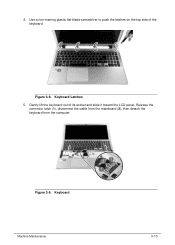
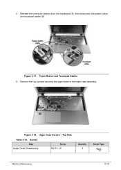
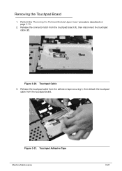
Acer Aspire V5-531 Notebook Service Guide
Page 23
Hardware Specifications and Configurations 1-15 Base View Table 1-5. Base View No. 1 2 Icon Item Battery pack Battery release latch Description Provides power to the computer when the power cord is unplugged. Releases the battery for removal. 3 DIMM compartment Houses the computer's memory modules. 4 Speaker Outputs sounds. 0 Base View 0 Figure 1-5.
Acer Aspire V5-531 Notebook Service Guide
Page 37
...5x 8x 8x 8x 8x 8x 8x 8x - 8x 24x 24x 16x 24x - 24x 2 MB Tray loading Electrical release (by eject button) Release by ATAPI command Emergency release (by emergency eject hole) 5 VDC ±0.25% Card Reader Item Controller Cards supported Manufacturing technology Specification RTL8411 ...DVD+R DVD+R DL DVD+RW DVD-ROM Single Layer DVD-ROM Dual Layer CD-R CD-RW CD-ROM Buffer memory Loading mechanism Release mechanism Power requirement Specification HLDS Super-Multi DRIVE 9.0mm Tray 8X GU61N LF+HF W/O bezel SATA Slim-type SATA Read 5x 8x ...
Acer Aspire V5-531 Notebook Service Guide
Page 71
... loading BIOS Flash, do not boot system. If battery pack does not contain power to update the system BIOS Flash ROM. Turn off the computer. 4. Release the Fn + Esc keys after POST. NOTE: NOTE: Do not install memory related drivers (XMS, EMS, DPMI) when Flash is used . NOTE: NOTE: Flash utility...
Acer Aspire V5-531 Notebook Service Guide
Page 85
Lift the battery pack from its bay. Turn the computer over so that the base is facing up. 2. Slide and hold the battery release latch to release the battery pack. 3. Figure 3-3. Detach the battery and follow local regulations for disposal. Battery Pack NOTE: NOTE: The battery has been highlighted with the yellow rectangle in Figure 3-3. Removing the Battery Pack 0 1. Machine Maintenance 3-9
Acer Aspire V5-531 Notebook Service Guide
Page 86
Perform the "Removing the Battery Pack" procedure described on the base door's notch to the lower case assembly. Remove the two screws securing the DIMM cover to release the DIMM cover, and then detach the cover from the computer. 3-10 Figure 3-5. Insert a non-marring plastic scribe on page 3-9. 2. DIMM Cover Screws Table 3-4. Screws Step DIMM Cover Disassembly Screw M2.5 × L5 Quantity 2 Screw Type 3. Figure 3-4. Removing the DIMM Cover 0 1. DIMM Cover Machine Maintenance
Acer Aspire V5-531 Notebook Service Guide
Page 89
Keyboard Latches 5. Figure 3-9. Gently lift the keyboard out of the keyboard. Release the connector latch (1), disconnect the cable from the mainboard (2), then detach the keyboard from the computer. Figure 3-8. Keyboard Machine Maintenance 3-13 Use a non-marring plastic flat-blade screwdriver to push the latches on the top side of its socket and slide it toward the LCD panel. 4.
Acer Aspire V5-531 Notebook Service Guide
Page 95
Remove the four screws securing the upper case to the lower case assembly. Upper Case Screws - Power Button and Touchpad Cables 5. Top Side Table 3-18. 4. Release the connector latches from the mainboard (1), then disconnect the power button and touchpad cables (2). Screws Step Upper Case Disassembly Screw M2.5 × L5 Quantity 4 Screw Type Machine Maintenance 3-19 Figure 3-17. Figure 3-18.
Acer Aspire V5-531 Notebook Service Guide
Page 97
Touchpad Cable 3. Figure 3-21. Perform the "Removing the Palmrest Module/Upper Case" procedure described on page 3-18. 2. Release the connector latch from the touchpad board. Figure 3-20. Release the touchpad cable from the adhesive tape securing it, then detach the touchpad cable from the touchpad board (1), then disconnect the touchpad cable (2). Removing the Touchpad Board 0 1. Touchpad Adhesive Tape Machine Maintenance 3-21
Acer Aspire V5-531 Notebook Service Guide
Page 99
Screw Step Power Button Board Disassembly Screw M2 × L3 Machine Maintenance Quantity 1 Screw Type 3-23 Power Button Board Screw Table 3-25. Release the connector latch from the power button board (1), then disconnect the power button cable (2). Figure 3-25. Figure 3-24. Remove the screw securing the power button board to the upper case. Turn the upper case over. 4. Power Button Cable 3. Removing the Power Button Board 0 1. Perform the "Removing the Palmrest Module/Upper Case" procedure described on page 3-18. 2.
Acer Aspire V5-531 Notebook Service Guide
Page 105
... described on page 3-25. 4. Perform the "Removing the SATA Board" procedure described on page 3-18. 2. Figure 3-34. Turn the computer over to acces the mainboard. 8. Release the LCD cable from the adhesive tape securing it (1), then disconnect the cable from the main board. Figure 3-35. Perform the "Removing the ODD Module...
Acer Aspire V5-531 Notebook Service Guide
Page 114
Gently pull out the WLAN antenna cables from the latches. remove the adhesive tapes securing the cables and release the cables from lower case; Figure 3-49. Remove the two screws securing the LCD module. LCD Module Hinge Screws Table 3-49. Perform the "Removing the Mainboard" procedure described on page 3-29. 2. Latches and Adhesive Tapes 3. Figure 3-48. Screws Step LCD Module Disassembly Screw M2 ×3 M2.5 ×L5 3-38 Quantity 1 1 Screw Type Machine Maintenance WLAN Antenna Cables - Removing the LCD Module 0 1.
Acer Aspire V5-531 Notebook Service Guide
Page 119
Screws Step LCD Panel Disassembly Screw M2 x L3 Quantity 4 Screw Type 3. Release the LCD cable from the latch located near the hinge (1), then gently lift the LCD panel (2). Figure 3-56. Removing the LCD Panel 0 1. LCD Panel Screws Table 3-55. Figure 3-55. LCD Cable Machine Maintenance 3-43 Remove the four screws securing the LCD panel to the LCD back cover. Perform the "Removing the LCD Bezel" procedure described on page 3-41. 2.
Acer Aspire V5-531 Notebook Service Guide
Page 122
Microphone 3-46 Machine Maintenance Gently pry the microphone off the LCD back panel. Figure 3-62. Release the microphone cable from the adhesive tapes securing them. Perform the "Removing the LCD Panel" procedure described on page 3-43. 2. Figure 3-61. Microphone Adhesive Tapes 3. Removing the Microphone 0 1.
Acer Aspire V5-531 Notebook Service Guide
Page 221
Test Compatible Components This computer's compatibility is tested and verified by the Acer Mobile System Testing Department. Regarding configuration, combination and test procedures, please refer to the following lists for components, adapter cards, and peripherals which...Codec 10004786 REALTEK Battery 60001921 SANYO Camera 10001023 LITE-ON 10001044 CHICONY PLM00012 Suyin Type Description Part No. Refer to the Compatibility Test Report released by Acer's internal testing department. LAN/VGA combo LAN/VGA combo port cable port cable NC.23811.003 65W 65W 65W "Adapter DELTA 65W 19V ...