Acer Aspire V5-531 Notebook Service Guide
Page 6
...BIOS Passwords 2-17 LAN EEPROM Utility 2-18 Machine Maintenance 5 Machine Disassembly and Replacement 3-5 Recommended Equipment 3-5 Replacement Requirements 3-5 Pre-disassembly Instructions 3-6 Disassembly Process 3-7 External Module Disassembly Process 3-8 External Modules Disassembly Flowchart 3-8 Removing the Battery Pack 3-9 Removing the DIMM Cover ... DIMM Modules 3-11 Removing the Keyboard 3-12 Removing the ODD Module 3-14 Main Unit Disassembly Process 3-17 Main Unit Disassembly Flowchart 3-17 Removing the Palmrest Module/Upper Case 3-18 Removing the Touchpad Board 3-21 ...
...BIOS Passwords 2-17 LAN EEPROM Utility 2-18 Machine Maintenance 5 Machine Disassembly and Replacement 3-5 Recommended Equipment 3-5 Replacement Requirements 3-5 Pre-disassembly Instructions 3-6 Disassembly Process 3-7 External Module Disassembly Process 3-8 External Modules Disassembly Flowchart 3-8 Removing the Battery Pack 3-9 Removing the DIMM Cover ... DIMM Modules 3-11 Removing the Keyboard 3-12 Removing the ODD Module 3-14 Main Unit Disassembly Process 3-17 Main Unit Disassembly Flowchart 3-17 Removing the Palmrest Module/Upper Case 3-18 Removing the Touchpad Board 3-21 ...
Acer Aspire V5-531 Notebook Service Guide
Page 43
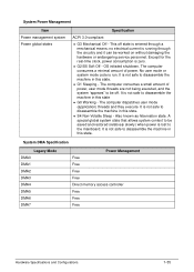
...a minimal amount of power, user mode threads are not being executed, and the system "appears" to be off state is not safe to disassemble the machine in this state. S4 Non-Volatile Sleep - The computer consumes a small amount of power. A special global system state that...Free Free Free Free Direct memory access controller Free Free Free Hardware Specifications and Configurations 1-35 This off . It is not safe to disassemble the machine in this state. It is entered through the circuitry and it can be saved and restored (relatively slowly) when power ...
...a minimal amount of power, user mode threads are not being executed, and the system "appears" to be off state is not safe to disassemble the machine in this state. S4 Non-Volatile Sleep - The computer consumes a small amount of power. A special global system state that...Free Free Free Free Direct memory access controller Free Free Free Hardware Specifications and Configurations 1-35 This off . It is not safe to disassemble the machine in this state. It is entered through the circuitry and it can be saved and restored (relatively slowly) when power ...
Acer Aspire V5-531 Notebook Service Guide
Page 78
... the DIMM Cover 3-10 Removing the DIMM Modules 3-11 Removing the Keyboard 3-12 Removing the ODD Module 3-14 Main Unit Disassembly Process 3-17 Main Unit Disassembly Flowchart 3-17 Removing the Palmrest Module/Upper Case 3-18 Removing the Touchpad Board 3-21 Removing the Power Button Board 3-23... Module 3-34 Removing the Battery Connector 3-35 Removing the Speaker Module 3-36 Removing the LCD Module 3-38 LCD Module Disassembly Process 3-40 LCD Module Disassembly Flowchart 3-40 Removing the LCD Bezel 3-41 Removing the Camera Board 3-42 Removing the LCD Panel 3-43 Removing the LCD...
... the DIMM Cover 3-10 Removing the DIMM Modules 3-11 Removing the Keyboard 3-12 Removing the ODD Module 3-14 Main Unit Disassembly Process 3-17 Main Unit Disassembly Flowchart 3-17 Removing the Palmrest Module/Upper Case 3-18 Removing the Touchpad Board 3-21 Removing the Power Button Board 3-23... Module 3-34 Removing the Battery Connector 3-35 Removing the Speaker Module 3-36 Removing the LCD Module 3-38 LCD Module Disassembly Process 3-40 LCD Module Disassembly Flowchart 3-40 Removing the LCD Bezel 3-41 Removing the Camera Board 3-42 Removing the LCD Panel 3-43 Removing the LCD...
Acer Aspire V5-531 Notebook Service Guide
Page 81
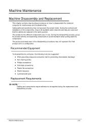
...;Cyanoacrylate glue Replacement Requirements 0 NOTE: NOTE: Cabling and components require adhesive to be applied during the replacement and reassembly process. Machine Maintenance 3-5 Machine Maintenance Machine Disassembly and Replacement 0 This chapter contains step-by-step procedures on how to avoid mismatch when putting back the components. The product previews seen in the...
...;Cyanoacrylate glue Replacement Requirements 0 NOTE: NOTE: Cabling and components require adhesive to be applied during the replacement and reassembly process. Machine Maintenance 3-5 Machine Maintenance Machine Disassembly and Replacement 0 This chapter contains step-by-step procedures on how to avoid mismatch when putting back the components. The product previews seen in the...
Acer Aspire V5-531 Notebook Service Guide
Page 82
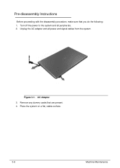
Place the system on a flat, stable surface. 3-6 Machine Maintenance Remove any dummy cards that you do the following: 1. Turn off the power to the system and all power and signal cables from the system. Pre-disassembly Instructions 0 Before proceeding with the disassembly procedure, make sure that are present. 4. Unplug the AC adapter and all peripherals. 2. AC Adapter 3. Figure 3-1.
Place the system on a flat, stable surface. 3-6 Machine Maintenance Remove any dummy cards that you do the following: 1. Turn off the power to the system and all power and signal cables from the system. Pre-disassembly Instructions 0 Before proceeding with the disassembly procedure, make sure that are present. 4. Unplug the AC adapter and all peripherals. 2. AC Adapter 3. Figure 3-1.
Acer Aspire V5-531 Notebook Service Guide
Page 83
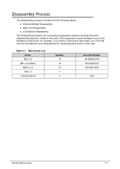
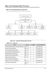
....5 x L5 M2 x 3 Thermal Screw Quantity 10 10 27 1 5 Acer Part Number 86.9A552.3R0 86.00J40.323 86.00J51.535 N/A Machine Maintenance 3-7 Disassembly Process 0 The disassembly process is divided into the following stages: External Module Disassembly Main Unit Disassembly LCD Module Disassembly The flowcharts provided in that order. For example...
....5 x L5 M2 x 3 Thermal Screw Quantity 10 10 27 1 5 Acer Part Number 86.9A552.3R0 86.00J40.323 86.00J51.535 N/A Machine Maintenance 3-7 Disassembly Process 0 The disassembly process is divided into the following stages: External Module Disassembly Main Unit Disassembly LCD Module Disassembly The flowcharts provided in that order. For example...
Acer Aspire V5-531 Notebook Service Guide
Page 84
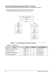
External Module Disassembly Process 0 External Modules Disassembly Flowchart 0 REMOVE BATTERY PACK DIMM COVER DIMM MODULES KEYBOARD ODD MODULE ODD BRACKET Figure 3-2. External Modules Disassembly Flowchart Table 3-2. Screw List Step DIMM Cover Disassembly ODD Disassembly ODD Bracket Disassembly Keyboard Disassembly Screw M2.5 x L5 M2.5 × L5 M2 × L3 M2.5 × L5 Quantity 2 1 2 2 Acer Part Number 86.00J51.535 86.00J51.535 86.9A552.3R0 86.00J51.535 3-8 Machine Maintenance
External Module Disassembly Process 0 External Modules Disassembly Flowchart 0 REMOVE BATTERY PACK DIMM COVER DIMM MODULES KEYBOARD ODD MODULE ODD BRACKET Figure 3-2. External Modules Disassembly Flowchart Table 3-2. Screw List Step DIMM Cover Disassembly ODD Disassembly ODD Bracket Disassembly Keyboard Disassembly Screw M2.5 x L5 M2.5 × L5 M2 × L3 M2.5 × L5 Quantity 2 1 2 2 Acer Part Number 86.00J51.535 86.00J51.535 86.9A552.3R0 86.00J51.535 3-8 Machine Maintenance
Acer Aspire V5-531 Notebook Service Guide
Page 86
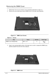
Perform the "Removing the Battery Pack" procedure described on the base door's notch to the lower case assembly. DIMM Cover Screws Table 3-4. Screws Step DIMM Cover Disassembly Screw M2.5 × L5 Quantity 2 Screw Type 3. Insert a non-marring plastic scribe on page 3-9. 2. Removing the DIMM Cover 0 1. Remove the two screws securing the DIMM cover to release the DIMM cover, and then detach the cover from the computer. 3-10 Figure 3-5. Figure 3-4. DIMM Cover Machine Maintenance
Perform the "Removing the Battery Pack" procedure described on the base door's notch to the lower case assembly. DIMM Cover Screws Table 3-4. Screws Step DIMM Cover Disassembly Screw M2.5 × L5 Quantity 2 Screw Type 3. Insert a non-marring plastic scribe on page 3-9. 2. Removing the DIMM Cover 0 1. Remove the two screws securing the DIMM cover to release the DIMM cover, and then detach the cover from the computer. 3-10 Figure 3-5. Figure 3-4. DIMM Cover Machine Maintenance
Acer Aspire V5-531 Notebook Service Guide
Page 88
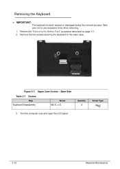
Base Side Table 3-7. Figure 3-7. Take care not to the lower case. Perform the "Removing the Battery Pack" procedure described on page 3-9. 2. Screws Step Keyboard Disassembly Screw M2.5 × L5 Quantity 2 Screw Type 3. Upper Case Screws - Remove the two screws securing the keyboard to use excessive force when removing. 1. Turn the computer over and open the LCD panel. 3-12 Machine Maintenance Removing the Keyboard 0 + IMPORTANT: The keyboard is easily warped or damaged during the removal process.
Base Side Table 3-7. Figure 3-7. Take care not to the lower case. Perform the "Removing the Battery Pack" procedure described on page 3-9. 2. Screws Step Keyboard Disassembly Screw M2.5 × L5 Quantity 2 Screw Type 3. Upper Case Screws - Remove the two screws securing the keyboard to use excessive force when removing. 1. Turn the computer over and open the LCD panel. 3-12 Machine Maintenance Removing the Keyboard 0 + IMPORTANT: The keyboard is easily warped or damaged during the removal process.
Acer Aspire V5-531 Notebook Service Guide
Page 90
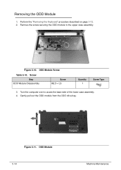
Removing the ODD Module 0 1. Figure 3-10. Turn the computer over to the upper case assembly. Figure 3-11. ODD Module Screw Table 3-10. Screw Step ODD Module Disassembly Screw M2.5 × L5 Quantity 1 Screw Type 3. Remove the screw securing the ODD module to acces the base side of the lower case assembly. 4. Gently pull out the ODD module from the ODD drive bay. Perform the "Removing the Keyboard" procedure described on page 3-12. 2. ODD Module 3-14 Machine Maintenance
Removing the ODD Module 0 1. Figure 3-10. Turn the computer over to the upper case assembly. Figure 3-11. ODD Module Screw Table 3-10. Screw Step ODD Module Disassembly Screw M2.5 × L5 Quantity 1 Screw Type 3. Remove the screw securing the ODD module to acces the base side of the lower case assembly. 4. Gently pull out the ODD module from the ODD drive bay. Perform the "Removing the Keyboard" procedure described on page 3-12. 2. ODD Module 3-14 Machine Maintenance
Acer Aspire V5-531 Notebook Service Guide
Page 91
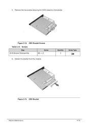
5. Quantity 2 Screw Type Figure 3-13. Screws Step ODD Bracket Disassembly Screw M2 × L3 6. Figure 3-12. ODD Bracket Screws Table 3-12. ODD Bracket Machine Maintenance 3-15 Detach the bracket from the module. Remove the two screws securing the ODD module to the bracket.
5. Quantity 2 Screw Type Figure 3-13. Screws Step ODD Bracket Disassembly Screw M2 × L3 6. Figure 3-12. ODD Bracket Screws Table 3-12. ODD Bracket Machine Maintenance 3-15 Detach the bracket from the module. Remove the two screws securing the ODD module to the bracket.
Acer Aspire V5-531 Notebook Service Guide
Page 93
... Case Disassembly Touchpad Board Disassembly Power Button Board Disassembly WLAN Module Disassembly Speaker Module Disassembly Mainboard Disassembly Thermal Module Disassembly Battery Connector Disassembly LCD Module Disassembly Screw M2.5 × L5 M2.5 × L5 M2 × L3 M2 × L3 M2 × L3 M2 × L3 M2 × L3 - M2 × L3 M2.5 × L5 M2 × 3 Quantity 17 3 3 1 1 4 1 5 2 1 1 Acer Part...
... Case Disassembly Touchpad Board Disassembly Power Button Board Disassembly WLAN Module Disassembly Speaker Module Disassembly Mainboard Disassembly Thermal Module Disassembly Battery Connector Disassembly LCD Module Disassembly Screw M2.5 × L5 M2.5 × L5 M2 × L3 M2 × L3 M2 × L3 M2 × L3 M2 × L3 - M2 × L3 M2.5 × L5 M2 × 3 Quantity 17 3 3 1 1 4 1 5 2 1 1 Acer Part...
Acer Aspire V5-531 Notebook Service Guide
Page 94
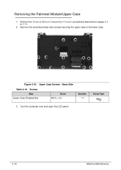
Figure 3-16. Upper Case Screws - Base Side Table 3-16. Remove the seventeen base side screws securing the upper case to 3-12. 2. Screws Step Upper Case Disassembly Screw M2.5 × L5 Quantity 17 Screw Type 3. Removing the Palmrest Module/Upper Case 0 1. Turn the computer over and open the LCD panel. 3-18 Machine Maintenance Perform the "External Module Disassembly Process" procedures described on pages 3-8 to the lower case.
Figure 3-16. Upper Case Screws - Base Side Table 3-16. Remove the seventeen base side screws securing the upper case to 3-12. 2. Screws Step Upper Case Disassembly Screw M2.5 × L5 Quantity 17 Screw Type 3. Removing the Palmrest Module/Upper Case 0 1. Turn the computer over and open the LCD panel. 3-18 Machine Maintenance Perform the "External Module Disassembly Process" procedures described on pages 3-8 to the lower case.
Acer Aspire V5-531 Notebook Service Guide
Page 95
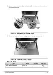
Top Side Table 3-18. Screws Step Upper Case Disassembly Screw M2.5 × L5 Quantity 4 Screw Type Machine Maintenance 3-19 Figure 3-17. Power Button and Touchpad Cables 5. Remove the four screws securing the upper case to the lower case assembly. Upper Case Screws - Release the connector latches from the mainboard (1), then disconnect the power button and touchpad cables (2). 4. Figure 3-18.
Top Side Table 3-18. Screws Step Upper Case Disassembly Screw M2.5 × L5 Quantity 4 Screw Type Machine Maintenance 3-19 Figure 3-17. Power Button and Touchpad Cables 5. Remove the four screws securing the upper case to the lower case assembly. Upper Case Screws - Release the connector latches from the mainboard (1), then disconnect the power button and touchpad cables (2). 4. Figure 3-18.
Acer Aspire V5-531 Notebook Service Guide
Page 98
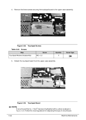
Remove the three screws securing the touchpad board to the upper case assembly. Detach the touchpad board from the upper case assembly. Touchpad Board NOTE: NOTE: A circuit board that is > 10cm2 has been highlighted with a yellow rectangle in Figure 3-23. Figure 3-22. Screws Step Touchpad Module Disassembly Screw M2 × L3 Quantity 3 5. Screw Type Figure 3-23. Follow the local regulations for disposing this type of circuit board. 3-22 Machine Maintenance Touchpad Screws Table 3-22. 4.
Remove the three screws securing the touchpad board to the upper case assembly. Detach the touchpad board from the upper case assembly. Touchpad Board NOTE: NOTE: A circuit board that is > 10cm2 has been highlighted with a yellow rectangle in Figure 3-23. Figure 3-22. Screws Step Touchpad Module Disassembly Screw M2 × L3 Quantity 3 5. Screw Type Figure 3-23. Follow the local regulations for disposing this type of circuit board. 3-22 Machine Maintenance Touchpad Screws Table 3-22. 4.
Acer Aspire V5-531 Notebook Service Guide
Page 99
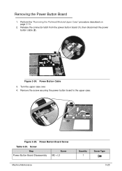
Perform the "Removing the Palmrest Module/Upper Case" procedure described on page 3-18. 2. Turn the upper case over. 4. Screw Step Power Button Board Disassembly Screw M2 × L3 Machine Maintenance Quantity 1 Screw Type 3-23 Figure 3-24. Power Button Board Screw Table 3-25. Release the connector latch from the power button board (1), then disconnect the power button cable (2). Remove the screw securing the power button board to the upper case. Removing the Power Button Board 0 1. Figure 3-25. Power Button Cable 3.
Perform the "Removing the Palmrest Module/Upper Case" procedure described on page 3-18. 2. Turn the upper case over. 4. Screw Step Power Button Board Disassembly Screw M2 × L3 Machine Maintenance Quantity 1 Screw Type 3-23 Figure 3-24. Power Button Board Screw Table 3-25. Release the connector latch from the power button board (1), then disconnect the power button cable (2). Remove the screw securing the power button board to the upper case. Removing the Power Button Board 0 1. Figure 3-25. Power Button Cable 3.
Acer Aspire V5-531 Notebook Service Guide
Page 101
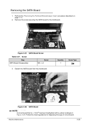
SATA Board Screw Table 3-27. Quantity 1 Screw Type Figure 3-28. SATA Board NOTE: NOTE: A circuit board that is > 10cm2 has been highlighted with a yellow rectangle in Figure 3-28. Perform the "Removing the Palmrest Module/Upper Case" procedure described on page 3-18. 2. Figure 3-27. Screw Step SATA Board Disassembly Screw M2 × L3 3. Remove the screw securing the SATA board to the mainboard. Removing the SATA Board 0 1. Follow the local regulations for disposing this type of circuit board. Detach the SATA board from the mainboard. Machine Maintenance 3-25
SATA Board Screw Table 3-27. Quantity 1 Screw Type Figure 3-28. SATA Board NOTE: NOTE: A circuit board that is > 10cm2 has been highlighted with a yellow rectangle in Figure 3-28. Perform the "Removing the Palmrest Module/Upper Case" procedure described on page 3-18. 2. Figure 3-27. Screw Step SATA Board Disassembly Screw M2 × L3 3. Remove the screw securing the SATA board to the mainboard. Removing the SATA Board 0 1. Follow the local regulations for disposing this type of circuit board. Detach the SATA board from the mainboard. Machine Maintenance 3-25
Acer Aspire V5-531 Notebook Service Guide
Page 103
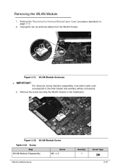
Remove the screw securing the WLAN module to the main (black) and auxiliary (white) connectors. 3. Removing the WLAN Module 0 1. Unplug the two (2) antenna cables from the WLAN module. WLAN Module Antennas + IMPORTANT: For reference during machine reassembly, note which cable color corresponds to the mainboard. Figure 3-31. Screw Step WLAN Module Disassembly Screw M2 × L3 Machine Maintenance Quantity 1 Screw Type 3-27 Figure 3-32. WLAN Module Screw Table 3-32. Perform the "Removing the Palmrest Module/Upper Case" procedure described on page 3-18. 2.
Remove the screw securing the WLAN module to the main (black) and auxiliary (white) connectors. 3. Removing the WLAN Module 0 1. Unplug the two (2) antenna cables from the WLAN module. WLAN Module Antennas + IMPORTANT: For reference during machine reassembly, note which cable color corresponds to the mainboard. Figure 3-31. Screw Step WLAN Module Disassembly Screw M2 × L3 Machine Maintenance Quantity 1 Screw Type 3-27 Figure 3-32. WLAN Module Screw Table 3-32. Perform the "Removing the Palmrest Module/Upper Case" procedure described on page 3-18. 2.
Acer Aspire V5-531 Notebook Service Guide
Page 106
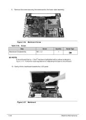
Screw Step Mainboard Disassembly Screw M2 × L3 Quantity 1 Screw Type NOTE: NOTE: A circuit board that is > 10cm2 has been highlighted with a yellow rectangle in Figure 3-37. Remove the screw securing the mainboard to the lower case assembly. Mainboard Screw Table 3-36. Gently tilt the mainboard towards the LCD panel. Figure 3-37. Follow the local regulations for disposing this type of circuit board. 10. Mainboard 3-30 Machine Maintenance Figure 3-36. 9.
Screw Step Mainboard Disassembly Screw M2 × L3 Quantity 1 Screw Type NOTE: NOTE: A circuit board that is > 10cm2 has been highlighted with a yellow rectangle in Figure 3-37. Remove the screw securing the mainboard to the lower case assembly. Mainboard Screw Table 3-36. Gently tilt the mainboard towards the LCD panel. Figure 3-37. Follow the local regulations for disposing this type of circuit board. 10. Mainboard 3-30 Machine Maintenance Figure 3-36. 9.
Acer Aspire V5-531 Notebook Service Guide
Page 108
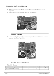
Fan Cable 3. Thermal Module Screws Table 3-40. Disconnect the thermal module fan cable from the mainboard. Loosen the spring-loaded captive screws securing the thermal module. Screws Step Thermal Module Disassembly Screw - 3-32 Quantity 5 Screw Type - Figure 3-39. Follow the screw sequence indicated on page 3-29. 2. Removing the Thermal Module 0 1. Machine Maintenance Perform the "Removing the Mainboard" procedure described on the preceding on Figure 3-40. Figure 3-40.
Fan Cable 3. Thermal Module Screws Table 3-40. Disconnect the thermal module fan cable from the mainboard. Loosen the spring-loaded captive screws securing the thermal module. Screws Step Thermal Module Disassembly Screw - 3-32 Quantity 5 Screw Type - Figure 3-39. Follow the screw sequence indicated on page 3-29. 2. Removing the Thermal Module 0 1. Machine Maintenance Perform the "Removing the Mainboard" procedure described on the preceding on Figure 3-40. Figure 3-40.


