Service Guide
Page 1
Acer Aspire R3700 Service Guide PRINTED IN TAIWAN
Acer Aspire R3700 Service Guide PRINTED IN TAIWAN

Service Guide
Page 2
Date Chapter Updates ii Revision History Please refer to the table below for the updates made on this service guide.
Date Chapter Updates ii Revision History Please refer to the table below for the updates made on this service guide.

Service Guide
Page 3
No part of this publication may be reproduced, transmitted, transcribed, stored in a retrieval system, or translated into any language or computer language, in any means, electronic, mechanical, magnetic, optical, chemical, manual or otherwise, without the prior written permission of Acer Incorporated. All rights reserved. iii Copyright Copyright © 2010 by any form or by Acer Incorporated.
No part of this publication may be reproduced, transmitted, transcribed, stored in a retrieval system, or translated into any language or computer language, in any means, electronic, mechanical, magnetic, optical, chemical, manual or otherwise, without the prior written permission of Acer Incorporated. All rights reserved. iii Copyright Copyright © 2010 by any form or by Acer Incorporated.
Service Guide
Page 4
...Duo, Core 2 Quad, Celeron, and combinations thereof, are trademarks and/or registered trademarks of their purchase, the buyer (and not Acer Incorporated, its distributor, or its dealer) assumes the entire cost of all necessary servicing, repair, and any incidental or consequential damages ... any defect in the software. Intel is a registered trademark of Intel Corporation. iv Acer is a registered trademark of merchantability or fitness for any warranties of Acer Corporation. Should the programs prove defective following their respective holders. Disclaimer The information in ...
...Duo, Core 2 Quad, Celeron, and combinations thereof, are trademarks and/or registered trademarks of their purchase, the buyer (and not Acer Incorporated, its distributor, or its dealer) assumes the entire cost of all necessary servicing, repair, and any incidental or consequential damages ... any defect in the software. Intel is a registered trademark of Intel Corporation. iv Acer is a registered trademark of merchantability or fitness for any warranties of Acer Corporation. Should the programs prove defective following their respective holders. Disclaimer The information in ...
Service Guide
Page 5
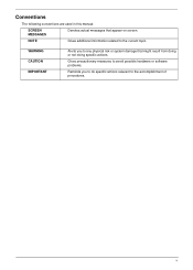
v NOTE Gives additional information related to the accomplishment of procedures. Conventions The following conventions are used in this manual: SCREEN MESSAGES Denotes actual messages that might result from doing or not doing specific actions. Gives precautionary measures to avoid possible hardware or software problems. Reminds you to any physical risk or system damage that appear on screen. WARNING CAUTION IMPORTANT Alerts you to do specific actions relevant to the current topic.
v NOTE Gives additional information related to the accomplishment of procedures. Conventions The following conventions are used in this manual: SCREEN MESSAGES Denotes actual messages that might result from doing or not doing specific actions. Gives precautionary measures to avoid possible hardware or software problems. Reminds you to any physical risk or system damage that appear on screen. WARNING CAUTION IMPORTANT Alerts you to do specific actions relevant to the current topic.

Service Guide
Page 6
... Please note WHEN ORDERING FRU PARTS, that you with all technical information relating to those given in the printed Service Guide. For ACER-AUTHORIZED SERVICE PROVIDERS, your regional web or channel. You MUST use the list provided by your regional office MAY have a DIFFERENT ... NOT be noted in the FRU list of a machine (e.g. To better fit local market requirements and enhance product competitiveness, your regional Acer office to extend the functionality of this generic service guide. In such cases, please contact your regional offices or the responsible personnel/channel...
... Please note WHEN ORDERING FRU PARTS, that you with all technical information relating to those given in the printed Service Guide. For ACER-AUTHORIZED SERVICE PROVIDERS, your regional web or channel. You MUST use the list provided by your regional office MAY have a DIFFERENT ... NOT be noted in the FRU list of a machine (e.g. To better fit local market requirements and enhance product competitiveness, your regional Acer office to extend the functionality of this generic service guide. In such cases, please contact your regional offices or the responsible personnel/channel...
Service Guide
Page 7
... 41 Checkpoints 42 BIOS Recovery 44 Jumper and Connector Information 45 M/B Placement 45 Jumper Setting 46 Setting Jumper 46 FRU (Field Replaceable Unit) List 53 Aspire R3700 Exploded Diagram 54 Aspire R3700 FRU List 55 vii
... 41 Checkpoints 42 BIOS Recovery 44 Jumper and Connector Information 45 M/B Placement 45 Jumper Setting 46 Setting Jumper 46 FRU (Field Replaceable Unit) List 53 Aspire R3700 Exploded Diagram 54 Aspire R3700 FRU List 55 vii

Service Guide
Page 8
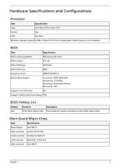
Operating System • Microsoft Windows 7 Home Premium X86/ X64 • Microsoft Windows 7 Home Basic X86/ X64 • Microsoft Windows 7 Starter x86 • Linux x-Window mode • Free DOS Processor • Socket Type: None • Processor Type: • Intel Atom D400/D500 series CPU • Atom D525+GT218 Chipset • Intel NM10 • Design Criteria: • Should meet Intel Pine Trial-D platform design guide • Super I/O: ITE/8721 • Should support SST signal output PCB • 170mm*170mm (Proprietary) Memory subsystem • Socket Type: DDR III SO-...
Operating System • Microsoft Windows 7 Home Premium X86/ X64 • Microsoft Windows 7 Home Basic X86/ X64 • Microsoft Windows 7 Starter x86 • Linux x-Window mode • Free DOS Processor • Socket Type: None • Processor Type: • Intel Atom D400/D500 series CPU • Atom D525+GT218 Chipset • Intel NM10 • Design Criteria: • Should meet Intel Pine Trial-D platform design guide • Super I/O: ITE/8721 • Should support SST signal output PCB • 170mm*170mm (Proprietary) Memory subsystem • Socket Type: DDR III SO-...
Service Guide
Page 9
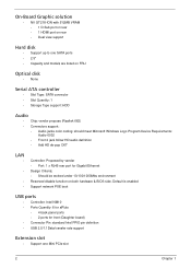
On-Board Graphic solution • NV GT218-ION with 512MB VRAM • 1 D-Sub port on rear • 1 HDMI port on rear • Dual view support Hard disk • Support up to one Mini PCIe slot 2 Chapter 1 Default is enabled Support network PXE boot USB ports • Controller: Intel NM10 • Ports Quantity: 6 for aPluto • 4 back panel ports • 2 ports for Gigabit Ethernet Design Criteria: • Should be worked under 10/100/1000Mbs environment Reserved disable function on FRU Optical disk • None Serial ATA controller • Slot Type: SATA connector &#...
On-Board Graphic solution • NV GT218-ION with 512MB VRAM • 1 D-Sub port on rear • 1 HDMI port on rear • Dual view support Hard disk • Support up to one Mini PCIe slot 2 Chapter 1 Default is enabled Support network PXE boot USB ports • Controller: Intel NM10 • Ports Quantity: 6 for aPluto • 4 back panel ports • 2 ports for Gigabit Ethernet Design Criteria: • Should be worked under 10/100/1000Mbs environment Reserved disable function on FRU Optical disk • None Serial ATA controller • Slot Type: SATA connector &#...
Service Guide
Page 10
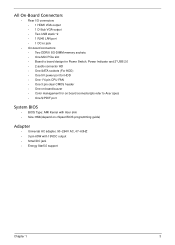
... 3 pin clear CMOS header • One on board buzzer • Color management for on board connecter(pls refer to Acer spec) • One S/PDIF port System BIOS • BIOS Type: AMI Kernel with Acer skin • Size: 8Mb(depend on chipset BIOS programming guide) Adapter • Universal AC adapter, 90~264V AC...
... 3 pin clear CMOS header • One on board buzzer • Color management for on board connecter(pls refer to Acer spec) • One S/PDIF port System BIOS • BIOS Type: AMI Kernel with Acer skin • Size: 8Mb(depend on chipset BIOS programming guide) Adapter • Universal AC adapter, 90~264V AC...
Service Guide
Page 12
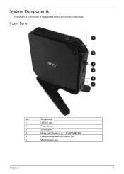
Component 1 USB 2.0 port 2 Power Button 3 S/PDIF port 4 Media Card Reader(4 in 1: XD/SD/MMC/MS) 5 Headphone/Speaker-out/line-out jack 6 Microphone-in jack Chapter 1 5 Front Panel 1 2 3 4 5 6 No. System Components This section is a virtual tour of the system's interior and exterior components.
Component 1 USB 2.0 port 2 Power Button 3 S/PDIF port 4 Media Card Reader(4 in 1: XD/SD/MMC/MS) 5 Headphone/Speaker-out/line-out jack 6 Microphone-in jack Chapter 1 5 Front Panel 1 2 3 4 5 6 No. System Components This section is a virtual tour of the system's interior and exterior components.
Service Guide
Page 14
... speed 0 MHz (If Stop CPU Clock in Sleep State in BIOS Setup is set to Enabled.) BIOS Item Specification BIOS code programmer AMI Kernel with Acer BIOS version P01-A0 BIOS ROM type SPI ROM BIOS ROM size 8MB Support protocol SMBIOS(DMI)2.6 Device Boot Support 1st priority: SATA HDD/SDD...
... speed 0 MHz (If Stop CPU Clock in Sleep State in BIOS Setup is set to Enabled.) BIOS Item Specification BIOS code programmer AMI Kernel with Acer BIOS version P01-A0 BIOS ROM type SPI ROM BIOS ROM size 8MB Support protocol SMBIOS(DMI)2.6 Device Boot Support 1st priority: SATA HDD/SDD...
Service Guide
Page 15
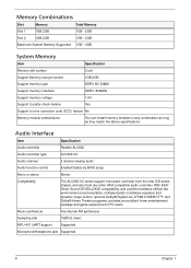
Memory Combinations Slot Memory Total Memory Slot 1 1GB,2GB 1GB ~2GB Slot 2 1GB,2GB 1GB ~2GB Maximum System Memory Supported 1GB ~4GB System Memory Item Specification Memory slot number 2 slot Support Memory size per socket 1GB,2GB Support memory type DDR3 SO-DIMM Support memory interface DDR3 800MHz Support memory voltage 1.5V Support to parity check feature Yes Support to error correction code (ECC) feature No Memory module combinations You can install memory modules in any other HDA compatible audio controller. Audio Interface Item Specification Audio ...
Memory Combinations Slot Memory Total Memory Slot 1 1GB,2GB 1GB ~2GB Slot 2 1GB,2GB 1GB ~2GB Maximum System Memory Supported 1GB ~4GB System Memory Item Specification Memory slot number 2 slot Support Memory size per socket 1GB,2GB Support memory type DDR3 SO-DIMM Support memory interface DDR3 800MHz Support memory voltage 1.5V Support to parity check feature Yes Support to error correction code (ECC) feature No Memory module combinations You can install memory modules in any other HDA compatible audio controller. Audio Interface Item Specification Audio ...
Service Guide
Page 16
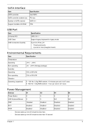
Power Management Devices S1 S3 S4 Power Button V V V USB Keyboard/Mouse V V N/A PME Disabled Disabled Disabled RCT Disabled Disabled Disabled WOR Disabled Disabled Disabled • Devices wake up from S3 should be less than. • Devices wake up from S5 should be less than 10 second S5 V N/A Disabled Disabled Disabled Chapter 1 9 SATA Interface Item SATA controller SATA controller resident bus Number of SATA channel Support bootable CD-ROM Specification Intel NM10 PCI bus SATA X 1 YES USB Port Item Universal HCI USB Class USB Connectors Quantity ...
Power Management Devices S1 S3 S4 Power Button V V V USB Keyboard/Mouse V V N/A PME Disabled Disabled Disabled RCT Disabled Disabled Disabled WOR Disabled Disabled Disabled • Devices wake up from S3 should be less than. • Devices wake up from S5 should be less than 10 second S5 V N/A Disabled Disabled Disabled Chapter 1 9 SATA Interface Item SATA controller SATA controller resident bus Number of SATA channel Support bootable CD-ROM Specification Intel NM10 PCI bus SATA X 1 YES USB Port Item Universal HCI USB Class USB Connectors Quantity ...
Service Guide
Page 17
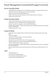
ACPI ACPI specification 1.0b S0,S1,S2 and S5 sleep state support. On board device power management support. On board device configuration support. 10 Chapter 1 Global Standby Mode • Global power management timer(2-120minutes,time step=10minute). • Hard disk drive goes into Standby mode(for ATA standard interface). • Disable H-sync and V-sync signals to control the VESA DPMS monitor. • Resume method: Resume to control the VESA DPMS monitor. • Resume method:device activated (keyboard for DOS, keyboard &mouse for ACPI mode. Power Management Function(...
ACPI ACPI specification 1.0b S0,S1,S2 and S5 sleep state support. On board device power management support. On board device configuration support. 10 Chapter 1 Global Standby Mode • Global power management timer(2-120minutes,time step=10minute). • Hard disk drive goes into Standby mode(for ATA standard interface). • Disable H-sync and V-sync signals to control the VESA DPMS monitor. • Resume method: Resume to control the VESA DPMS monitor. • Resume method:device activated (keyboard for DOS, keyboard &mouse for ACPI mode. Power Management Function(...
Service Guide
Page 18
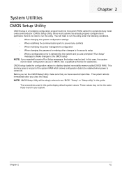
Since most systems are prompted ("Run Setup" message) to make sure that you repeatedly receive Run Setup messages, the battery may not be bad. You will be simply referred to be retained when power is turned off. These values may be the same those found in this guide. This memory area is not part of the system RAM which allows configuration data to as "BIOS", "Setup", or "Setup utility" in this guide display default system values. The screenshots used in your system. Ask a qualified technician for assistance. CMOS setup loads the configuration values in CMOS....
Since most systems are prompted ("Run Setup" message) to make sure that you repeatedly receive Run Setup messages, the battery may not be bad. You will be simply referred to be retained when power is turned off. These values may be the same those found in this guide. This memory area is not part of the system RAM which allows configuration data to as "BIOS", "Setup", or "Setup utility" in this guide display default system values. The screenshots used in your system. Ask a qualified technician for assistance. CMOS setup loads the configuration values in CMOS....
Service Guide
Page 19
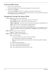
If the server is completed, you are not user-configurable. • Enter key - Use the left and right arrow keys to move between selections on the server and the monitor. Select a value for the currently selected field (only if it is indicated by a (>). • Esc - Press to load optimized default system values. • F7 - Navigating Through the Setup Utility Use the following keys to move around the Setup utility. • Left and Right arrow keys - Press these keys repeatedly to display each possible entry, or the Enter key to restart the server. Display a ...
If the server is completed, you are not user-configurable. • Enter key - Use the left and right arrow keys to move between selections on the server and the monitor. Select a value for the currently selected field (only if it is indicated by a (>). • Esc - Press to load optimized default system values. • F7 - Navigating Through the Setup Utility Use the following keys to move around the Setup utility. • Left and Right arrow keys - Press these keys repeatedly to display each possible entry, or the Enter key to restart the server. Display a ...
Service Guide
Page 20
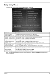
It allows you to limit access to the System Load Default Setting indicates the value of the system parameters which the system would be in best performance configuration Save CMOS value settings to CMOS and exit setup Abandon all the items of Green function features This setup page is the System auto detect Temperature, voltage, and fan speed This setup page is the System Frequency setup Change, set or disable password. Chapter 2 14 Parameter Product Information Standard CMOS Features Advanced Chipset Features Advanced Chipset Features Integrated Peripherals Power Management Setup PC...
It allows you to limit access to the System Load Default Setting indicates the value of the system parameters which the system would be in best performance configuration Save CMOS value settings to CMOS and exit setup Abandon all the items of Green function features This setup page is the System auto detect Temperature, voltage, and fan speed This setup page is the System Frequency setup Change, set or disable password. Chapter 2 14 Parameter Product Information Standard CMOS Features Advanced Chipset Features Advanced Chipset Features Integrated Peripherals Power Management Setup PC...
Service Guide
Page 21
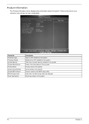
Version number of the system. Date when the BIOS setup utility was released Asset tag number of the CPU installed on the system. Speed of this system. Total size of this system. 15 Chapter 2 Serial number of the BIOS setup utility. Product Information The Product Information menu displays basic information about the system. Product name of CPU installed on the system. These entries are for your reference only and are not user-configurable. Parameter Processor Type Processor Speed System Memory System Manufacturer Product Name System Serial Number System BIOS Version ...
Version number of the system. Date when the BIOS setup utility was released Asset tag number of the CPU installed on the system. Speed of this system. Total size of this system. 15 Chapter 2 Serial number of the BIOS setup utility. Product Information The Product Information menu displays basic information about the system. Product name of CPU installed on the system. These entries are for your reference only and are not user-configurable. Parameter Processor Type Processor Speed System Memory System Manufacturer Product Name System Serial Number System BIOS Version ...
Service Guide
Page 22
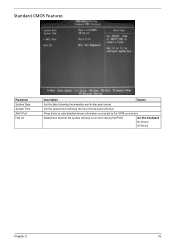
All, But Keyboard No Errors All Errors Chapter 2 16 Determines whether the system will stop for an error during the POST. Press Enter to view detailed device information connected to the SATA connectors. Standard CMOS Features Parameter System Date System Time AHCI Port Halt On Description Option Set the date following the hour-minute-second format. Set the system time following the weekday-month-day-year format.
All, But Keyboard No Errors All Errors Chapter 2 16 Determines whether the system will stop for an error during the POST. Press Enter to view detailed device information connected to the SATA connectors. Standard CMOS Features Parameter System Date System Time AHCI Port Halt On Description Option Set the date following the hour-minute-second format. Set the system time following the weekday-month-day-year format.