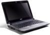
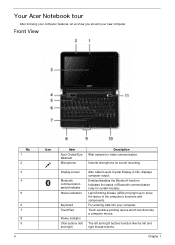
Aspire One 8.9-Inch Series (AOA) Quick Guide English
Page 12
Top view # Icon 1 Item Acer Crystal Eye webcam Description Web camera for video communication (only for Starters section, let us show you around your computer as illustrated in the Just for certain models). English 12 Your Aspire one tour After setting up your new Acer notebook.
Aspire One AOD150 Series Service Guide
Page 8
...76 LCD Module Disassembly Process 78 LCD Module Disassembly Flowchart 78 Removing the LCD Bracket Extensions 79 Removing the LCD Bezel 80 Removing the Camera Board 82 Removing the LCD Panel 83 Removing the LCD Brackets and FPC Cable 84 Removing the Microphone Board 86 Removing the... Camera Cable 87 Removing the Antennas 88 LCD Module Reassembly Procedure 89 Replacing the Antennas, Camera Cable, and MIC 89 Replacing the LCD Cable and Brackets 91 Replacing the LCD Panel 93 Replacing...
Aspire One AOD150 Series Service Guide
Page 14
... screen Bluetooth communication switch/indicator Status indicators Keyboard TouchPad Power indicator Click buttons (left and right mouse buttons. For entering data into your computer. Your Acer Notebook tour After knowing your computer features, let us show the status of Bluetooth communication (only for sound recording. Front View No. 1 2 3 4 5 6 7 8 9 4 Icon Item...
Aspire One AOD150 Series Service Guide
Page 27
Mini Card Item Number Supported Features Camera Item Vendor and model Type 3G Card Features Item Wireless LAN Type Features Item Battery Item Vendor & model name Battery Type Pack capacity Number of ... and 1 for WLAN or WLAN/ WiMax) • Embedded 3G module and built-in 1 antenna (combo wireless + 3G) on top/side of LCD Specification Suyin Camera Rosa Liteon Camera Lily 0.3M LDV Specification • 3G card in mini-PCI card size • Control by USB interface • User accessible SIM card by battery...
Aspire One AOD150 Series Service Guide
Page 73
Removing the LCD Module IMPORTANT: Cable paths and positioning may not represent the actual model. Carefully pull the antenna cables through from the underside of the LCD Module, ensure all available cable channels and clips are used and that the cables are replaced in place. 3. Disconnect the Camera cable from the cable clips. 4. See "Removing the Upper Cover" on page 54. 2. Chapter 3 63 During the removal and replacement of the computer and remove the cables from the Mainboard. Remove the adhesive strip securing the antenna cables in the same position. 1.
Aspire One AOD150 Series Service Guide
Page 88
... Main Unit before proceeding Rem ove LCD Bracket Extensions Rem ove LCD Bezel Rem ove LCD Panel Rem ove Camera Module Rem ove LCD FPC Cable Rem ove LCD Brackets Rem ove Camera Cable Rem ove Microphone Rem ove Antennas Screw List Step LCD Bezel LCD Panel LCD Brackets Screw M2*6 M2...
Aspire One AOD150 Series Service Guide
Page 92
Remove the Camera Board from the Camera Board as shown. 3. Disconnect the cable from the LCD Module. 82 Chapter 3 Removing the Camera Board 1. See "Removing the LCD Bezel" on page 80. 2.
Aspire One AOD150 Series Service Guide
Page 93
Place it on page 82. 2. See "Removing the Camera Board" on a clean surface. Hold the LCD Panel from the LCD Panel. Remove the two securing screws from the sides and lift to remove. Step LCD Panel Size M2*6 Quantity 2 Screw Type 3. Chapter 3 83 Removing the LCD Panel 1.
Aspire One AOD150 Series Service Guide
Page 97
Chapter 3 87 Remove the Camera cable from the LCD Module. Remove the adhesive strips holding the Camera cable in place. 3. Removing the Camera Cable 1. See "Removing the LCD Panel" on page 83. 2.
Aspire One AOD150 Series Service Guide
Page 99
Replace the Camera cable in place. LCD Module Reassembly Procedure Replacing the Antennas, Camera Cable, and MIC 1. Chapter 3 89 Replace the left and right Antenna cables as shown. Press the Camera cable down the Antenna pads to secure them to secure it in the LCD Module as shown. 4. Press down to the LCD Module (green callouts). 3. Ensure the cables run through all the available adhesive securing strips as shown. 2.
Aspire One AOD150 Series Service Guide
Page 100
shown. 7. Press the MIC Board down to secure it in place. Run the cable as clips and replace the adhesive strip (green callout). 5. Run the MIC cable along the LCD Module as shown when the Antennas, Camera Cable, and MIC Board are replaced correctly. 90 Chapter 3 Replace the MIC Board in the LCD Module as shown using all the available cable 6. NOTE: The LCD Module appears as shown and replace the adhesive strips to secure it in place. 8.
Aspire One AOD150 Series Service Guide
Page 104
Place the Camera Module in the LCD Module and press down to secure it in place. 2. Connect the Camera cable as shown. 94 Chapter 3 Replacing the Camera Module 1.
Aspire One AOD150 Series Service Guide
Page 115
Run the Camera cable along the Lower Cover using all available cable clips. 7. Run the Antenna cables along the Lower Cover using all available cable clips. 5. Pass the Antenna cables through the Lower Cover and them in place with an adhesive strip. Chapter 3 105 Connect the Camera cable to the Mainboard. 6. 4.
Aspire One AOD150 Series Service Guide
Page 162
....001 ANTENNA 3G-AUX ANTENNA 3G-WL/AUX LCD BEZEL 50.S5802.002 50.S5802.003 60.S5502.004 152 Chapter 6 Category LCD CABLE Description Acer PN 50.S5502.007 LCD BRACKET-R&L CAMERA MODULE-0.3M CMOS CABLE 33.S5502.003 57.S5502.001 50.S5502.008 ASSY LED MODULE 10.1 IN.
Aspire One AOD150 Series Service Guide
Page 224
Vendor Type 60001921 SANYO 6CELL2.6 60001921 SANYO 6CELL2.2 Bluetooth 9999995 ONE TIME VENDER BT 2.0 Camera 9999995 ONE TIME VENDER 0.3M LDV 9999995 ONE TIME VENDER 0.3M LDV Card Reader 9999995 ONE TIME VENDER 5 in 1-Build in CPU/Processor 10001067 INTEL ATMN270B 10001067 INTEL ATMN280B HDD 60002036 SEAGATE ... Black Battery SANYO UM-2008BW Li-Ion 3S2P SANYO 6 cell 4400mAh Main COMMON White, 2.2 Ah (A) Foxconn Bluetooth FOX_BRM_2.0 F/W 300 Suyin Camera Rosa Liteon Camera Lily 5 in 1-Build in MS, MS Pro, SD, SC, XD CPU Intel Atom N270 1.6G 512K 533 2.5W CPU Intel Atom...