Service Guide
Page 9
Table of Contents POST Code Reference Tables 143 Jumper and Connector Locations 147 Mainboard Top View 147 Mainboard Bottom View 148 Clearing Password Check and BIOS Recovery 149 Mainboard CMOS Discharge 149 BIOS Recovery by Crisis Disk 150 FRU (Field Replaceable Unit) List 151 Exploded Diagrams 151 Main Assembly 152 LCD Assembly 153 FRU List 154 Screw List 160 Model Definition and Configuration 161 Aspire 1810T/1410 161 Aspire One 752 219 Test Compatible Components 231 Aspire 1810T/1410 232 Aspire One 752 236 Online Support Information 241 Index 243 IX
Table of Contents POST Code Reference Tables 143 Jumper and Connector Locations 147 Mainboard Top View 147 Mainboard Bottom View 148 Clearing Password Check and BIOS Recovery 149 Mainboard CMOS Discharge 149 BIOS Recovery by Crisis Disk 150 FRU (Field Replaceable Unit) List 151 Exploded Diagrams 151 Main Assembly 152 LCD Assembly 153 FRU List 154 Screw List 160 Model Definition and Configuration 161 Aspire 1810T/1410 161 Aspire One 752 219 Test Compatible Components 231 Aspire 1810T/1410 232 Aspire One 752 236 Online Support Information 241 Index 243 IX
Service Guide
Page 141
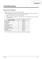
Obtain the failing symptoms in as much detail as a guide for computer problems. NOTE: The diagnostic tests are intended to test only Acer products. Symptoms (Verified) Go To Power On Issue Page 132 No Display Issue Page 133 LCD Failure Page 135 Internal ...241. Chapter 4 131 Use the following procedure as possible. 2. Verify the symptoms by attempting to re-create the failure by running the diagnostic test or by repeating the same operation. 3. Troubleshooting Chapter 4 Common Problems Use the following table with the verified symptom to determine which page to...
Obtain the failing symptoms in as much detail as a guide for computer problems. NOTE: The diagnostic tests are intended to test only Acer products. Symptoms (Verified) Go To Power On Issue Page 132 No Display Issue Page 133 LCD Failure Page 135 Internal ...241. Chapter 4 131 Use the following procedure as possible. 2. Verify the symptoms by attempting to re-create the failure by running the diagnostic test or by repeating the same operation. 3. Troubleshooting Chapter 4 Common Problems Use the following table with the verified symptom to determine which page to...
Service Guide
Page 149
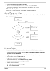
Internal Microphone Failure If the internal Microphone fails, perform the following actions one at a time to Start Control Panel Hardware and Sound ... 5. If the Issue is not fixed, repeat the preceding steps and select an earlier time and date. 10. Test the microphone hardware: a. Right-click on page 241. Chapter 4 139 Restore system and file settings from a known ... or external Microphones do no operate correctly, perform the following actions one at a time to the maximum setting and click OK. 7. Check that the microphone is enabled. 8.
Internal Microphone Failure If the internal Microphone fails, perform the following actions one at a time to Start Control Panel Hardware and Sound ... 5. If the Issue is not fixed, repeat the preceding steps and select an earlier time and date. 10. Test the microphone hardware: a. Right-click on page 241. Chapter 4 139 Restore system and file settings from a known ... or external Microphones do no operate correctly, perform the following actions one at a time to the maximum setting and click OK. 7. Check that the microphone is enabled. 8.
Service Guide
Page 150
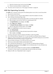
.... Run the Windows Disk Defragmenter. Replace the HDD. HDD Not Operating Correctly If the HDD does not operate correctly, perform the following actions one at a time to complete the test. 8. insert the Windows Vista Operating System DVD in the ODD and restart the computer. d. Select the appropriate operating system, and click Next...
.... Run the Windows Disk Defragmenter. Replace the HDD. HDD Not Operating Correctly If the HDD does not operate correctly, perform the following actions one at a time to complete the test. 8. insert the Windows Vista Operating System DVD in the ODD and restart the computer. d. Select the appropriate operating system, and click Next...

Service Guide
Page 151
USB Failure (Right up/down side) If the rightside USB port fails, perform the following general steps to correct the problem. Verify that the Test Fixture is OK. 2. Swap the mainboard and retest. Check whether the drive is ok. 3. Chapter 4 141 Do not replace non-defective FRUs: 1. Do not replace ... Failures If the VGA board, LAN Port, external MIC or Speakers, PCI Express Card, 5-in-1 Card Reader or Volume Wheel fail, perform the following actions one at a time to correct the problem.
USB Failure (Right up/down side) If the rightside USB port fails, perform the following general steps to correct the problem. Verify that the Test Fixture is OK. 2. Swap the mainboard and retest. Check whether the drive is ok. 3. Chapter 4 141 Do not replace non-defective FRUs: 1. Do not replace ... Failures If the VGA board, LAN Port, external MIC or Speakers, PCI Express Card, 5-in-1 Card Reader or Volume Wheel fail, perform the following actions one at a time to correct the problem.
Service Guide
Page 152
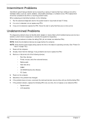
...detected, replace the FRU. If any FRU. 3. If the problem does not recur, reconnect the removed devices one at the time of reasons that all of the following devices: • Non-Acer devices • Printer, mouse, and other external devices • Battery pack • Hard disk drive &#...the problem has changed. 6. If the problem remains, replace the following : 1. Power-on page 132.): 1. Rerun the test to isolate the failing FRU (do the following FRU one at least 10 times. 2. When analyzing an intermittent problem, do not isolate non-defective FRU). If any error is ...
...detected, replace the FRU. If any FRU. 3. If the problem does not recur, reconnect the removed devices one at the time of reasons that all of the following devices: • Non-Acer devices • Printer, mouse, and other external devices • Battery pack • Hard disk drive &#...the problem has changed. 6. If the problem remains, replace the following : 1. Power-on page 132.): 1. Rerun the test to isolate the failing FRU (do the following FRU one at least 10 times. 2. When analyzing an intermittent problem, do not isolate non-defective FRU). If any error is ...

Service Guide
Page 241
Test Compatible Components Appendix B This computer's compatibility is tested and verified by the Acer Mobile System Testing Department Appendix B 231 Refer to the Aspire one series Compatibility Test Report released by Acer's internal testing department. Regarding configuration, combination and test procedures, please refer to the following lists for components, adapter cards, and peripherals which have passed these tests. All of its system functions are tested under Windows® XP Home, Windows® XP Pro environment.
Test Compatible Components Appendix B This computer's compatibility is tested and verified by the Acer Mobile System Testing Department Appendix B 231 Refer to the Aspire one series Compatibility Test Report released by Acer's internal testing department. Regarding configuration, combination and test procedures, please refer to the following lists for components, adapter cards, and peripherals which have passed these tests. All of its system functions are tested under Windows® XP Home, Windows® XP Pro environment.
Service Guide
Page 254
... 9 O ODD Failure 141 Online Support Information 241 P Panel 5 left 5 PC Card 9 Power On Failure 132 S Speaker Module Removing 68 speakers hotkey 13 System Block Diagram 4 T Test Compatible Components 231 Thermal Module Removing 74 Touch Pad Failure 137 Troubleshooting Built-in KB Failure 136 Internal Microphone 139 244 Internal Speakers 138 LCD... Pad 137 USB 141 U Undetermined Problems 142 Upper Cover Removing 58 USB Failure (Rightside) 141 utility BIOS 25-33 V volume hotkeys 13 W Windows 2000 Environment Test 232 WLAN Board Removing 52
... 9 O ODD Failure 141 Online Support Information 241 P Panel 5 left 5 PC Card 9 Power On Failure 132 S Speaker Module Removing 68 speakers hotkey 13 System Block Diagram 4 T Test Compatible Components 231 Thermal Module Removing 74 Touch Pad Failure 137 Troubleshooting Built-in KB Failure 136 Internal Microphone 139 244 Internal Speakers 138 LCD... Pad 137 USB 141 U Undetermined Problems 142 Upper Cover Removing 58 USB Failure (Rightside) 141 utility BIOS 25-33 V volume hotkeys 13 W Windows 2000 Environment Test 232 WLAN Board Removing 52

User Guide
Page 46
... device generates, uses, and can be determined by turning the device off and on, the user is encouraged to try to correct the interference by one or more of the following two conditions: (1) this device may cause undesired operation. Notice: Shielded cables All connections to other computing devices must accept any... with FCC regulations. Operation conditions This device complies with the limits for help. English 28 Regulations and safety notices FCC notice This device has been tested and found to comply with Part 15 of the FCC Rules.
... device generates, uses, and can be determined by turning the device off and on, the user is encouraged to try to correct the interference by one or more of the following two conditions: (1) this device may cause undesired operation. Notice: Shielded cables All connections to other computing devices must accept any... with FCC regulations. Operation conditions This device complies with the limits for help. English 28 Regulations and safety notices FCC notice This device has been tested and found to comply with Part 15 of the FCC Rules.

User Guide
Page 50
...Mobile Satellite systems. • High power radars are allocated as primary users (meaning they have priority) of luminance and color temperature @ 6500K (tested under BM7) Pixel fault class 500 mm 0.0° 90.0° Class IV 85.0° • Illuminance level: [250 + (250cosα...;)] lx where α = 85° • Color: Source D65 • Ordinary LCD: Class I • Protective or Acer CrystalBrite™ LCD: Class III Both • Yn • u'n • v'n Class II LCD panel ergonomic specifications Design viewing distance Design inclination angle Design...
...Mobile Satellite systems. • High power radars are allocated as primary users (meaning they have priority) of luminance and color temperature @ 6500K (tested under BM7) Pixel fault class 500 mm 0.0° 90.0° Class IV 85.0° • Illuminance level: [250 + (250cosα...;)] lx where α = 85° • Color: Source D65 • Ordinary LCD: Class I • Protective or Acer CrystalBrite™ LCD: Class III Both • Yn • u'n • v'n Class II LCD panel ergonomic specifications Design viewing distance Design inclination angle Design...
