Service Guide
Page 7
...System Tour Features Block Diagram System Components Front Panel Rear Panel Hardware Specifications and Configurations Power Management Function(ACPI support function) 1 1 4 5 5 6 7 10 System ...USB Board Removing the Cables Removing the System Fan Removing the Optical Drive Removing the Power Supply Removing the Memory Modules Removing the Removable HDD bay Removing the Mainboard 26 ...38 39 40 41 42 43 45 System Troubleshooting Hardware Diagnostic Procedure System Check Procedures Power System Check System External Inspection System Internal Inspection Beep Codes Checkpoints BIOS Recovery 46 ...
...System Tour Features Block Diagram System Components Front Panel Rear Panel Hardware Specifications and Configurations Power Management Function(ACPI support function) 1 1 4 5 5 6 7 10 System ...USB Board Removing the Cables Removing the System Fan Removing the Optical Drive Removing the Power Supply Removing the Memory Modules Removing the Removable HDD bay Removing the Mainboard 26 ...38 39 40 41 42 43 45 System Troubleshooting Hardware Diagnostic Procedure System Check Procedures Power System Check System External Inspection System Internal Inspection Beep Codes Checkpoints BIOS Recovery 46 ...
Service Guide
Page 11
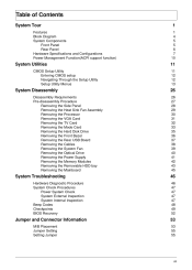
... 4 * USB H5X2 Header (support 8 ports) 1 * Front Audio Pannel H5X2 header 1 * Front Panel IO H7X2 Header for Acer pin define 1 * H1X4 CPU with SAMRT FAN controller 1 * H1X3 System with SAMRT FAN controller 1 * H1X4 SPDIFOUT Header for Acer pin define 1 * H3X1 Clear CMOS Header (with jumper) 1 * onboard Buzzer 2 * H1X2 GPIO header System BIOS •...
... 4 * USB H5X2 Header (support 8 ports) 1 * Front Audio Pannel H5X2 header 1 * Front Panel IO H7X2 Header for Acer pin define 1 * H1X4 CPU with SAMRT FAN controller 1 * H1X3 System with SAMRT FAN controller 1 * H1X4 SPDIFOUT Header for Acer pin define 1 * H3X1 Clear CMOS Header (with jumper) 1 * onboard Buzzer 2 * H1X2 GPIO header System BIOS •...

Service Guide
Page 13
System Components This section is a virtual tour of the system's interior and exterior components. Front Panel 9 1 8 7 2 6 3 4 5 No. 1 2 3 4 5 6 7 8 9 Component USB 2.0 ports Acer logo Optical drive button Optical drive button (Removable HDD bay for AM551 bezel) Removable HDD bay Power button 16 in 1 Card Reader Headphone/Speaker-out/line-out jack Microphone-in jack Chapter 1 5
System Components This section is a virtual tour of the system's interior and exterior components. Front Panel 9 1 8 7 2 6 3 4 5 No. 1 2 3 4 5 6 7 8 9 Component USB 2.0 ports Acer logo Optical drive button Optical drive button (Removable HDD bay for AM551 bezel) Removable HDD bay Power button 16 in 1 Card Reader Headphone/Speaker-out/line-out jack Microphone-in jack Chapter 1 5

Service Guide
Page 14
Rear Panel 1 13 2 12 11 3 10 4 9 5 6 7 8 No. 1 2 3 4 5 6 7 8 9 10 11 12 13 Component Power connector PS2 keyboard port VGA port USB 2.0 ports Mic-in Line-out Expansion slot (graphics card and TV tuner card and Mode card) Line-in USB 2.0 ports LAN connector System FAN PS2 mouse port Fan aperture 6 Chapter 1
Rear Panel 1 13 2 12 11 3 10 4 9 5 6 7 8 No. 1 2 3 4 5 6 7 8 9 10 11 12 13 Component Power connector PS2 keyboard port VGA port USB 2.0 ports Mic-in Line-out Expansion slot (graphics card and TV tuner card and Mode card) Line-in USB 2.0 ports LAN connector System FAN PS2 mouse port Fan aperture 6 Chapter 1
Service Guide
Page 17
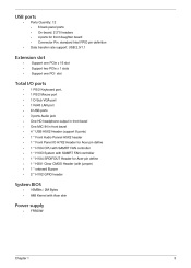
... random, 1 hour per axis in all 3 axes. 15% to 80% RH 10% to 90% RH +5°C ~ +35°C -20 ~ +60°C (Storage package) Specification Power Management Devices Power Button USB Keyboard/Mouse PME RCT WOR • • S1 V V Disabled Disabled Disabled S3 V V Disabled Disabled Disabled S4 V N/A Disabled Disabled Disabled S5 V N/A Disabled Disabled...
... random, 1 hour per axis in all 3 axes. 15% to 80% RH 10% to 90% RH +5°C ~ +35°C -20 ~ +60°C (Storage package) Specification Power Management Devices Power Button USB Keyboard/Mouse PME RCT WOR • • S1 V V Disabled Disabled Disabled S3 V V Disabled Disabled Disabled S4 V N/A Disabled Disabled Disabled S5 V N/A Disabled Disabled...
Service Guide
Page 18
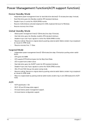
.... Disable H-sync and V-sync signals to control the VESA DPMS monitor. Resume recovery time :7-10sec • Suspend Mode • Independent power management timer(2-120minutes,time step=10minute)or pushing extern switch button. LED on panel turns amber colour. Resume method: Resume to original state... hard disk drive devices(0-15 minutes,time step=1minute). Ultra I/O and VGA chip go into the Stop Grant State. On board device power management support. Resume method: Resume to control the VESA DPMS monitor. Hard disk drive goes into Standby mode(for ACPI mode. •...
.... Disable H-sync and V-sync signals to control the VESA DPMS monitor. Resume recovery time :7-10sec • Suspend Mode • Independent power management timer(2-120minutes,time step=10minute)or pushing extern switch button. LED on panel turns amber colour. Resume method: Resume to original state... hard disk drive devices(0-15 minutes,time step=1minute). Ultra I/O and VGA chip go into the Stop Grant State. On board device power management support. Resume method: Resume to control the VESA DPMS monitor. Hard disk drive goes into Standby mode(for ACPI mode. •...
Service Guide
Page 19
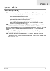
...Chapter 2 11 When changing the system configuration settings When redefining the communication ports to prevent any conflicts When modifying the power management configuration When changing the password or making other changes to run this utility under the following conditions. CMOS setup..." in a battery-backed nonvolatile memory called the complementary metaloxide semiconductor (CMOS) Setup Utility. These values may be retained when power is turned off. The system reboots immediately after you repeatedly receive Run Setup messages, the battery may not be simply referred to...
...Chapter 2 11 When changing the system configuration settings When redefining the communication ports to prevent any conflicts When modifying the power management configuration When changing the password or making other changes to run this utility under the following conditions. CMOS setup..." in a battery-backed nonvolatile memory called the complementary metaloxide semiconductor (CMOS) Setup Utility. These values may be retained when power is turned off. The system reboots immediately after you repeatedly receive Run Setup messages, the battery may not be simply referred to...

Service Guide
Page 21
Chapter 2 13 Parameter Product Information Standard CMOS Features Advanced BIOS Features Advanced Chipset Features Integrated Peripherals Power Management Setup PC Health Status Frequency/Voltage Control BIOS Security Features Load Default Setting Save & Exit Setup Exit Without Saving Description This page shows the ...
Chapter 2 13 Parameter Product Information Standard CMOS Features Advanced BIOS Features Advanced Chipset Features Integrated Peripherals Power Management Setup PC Health Status Frequency/Voltage Control BIOS Security Features Load Default Setting Save & Exit Setup Exit Without Saving Description This page shows the ...
Service Guide
Page 24
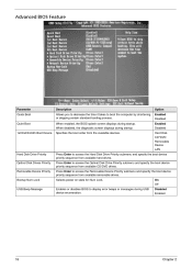
... Priority Optical Disk Drives Priority Removable Device Priority Bootup Num-Lock USB Beep Message Press Enter to display error beeps or messages during startup. Selects power on state for Num Lock. When disabled, the diagnostic screen displays during startup. Press Enter to boot the computer by shortening or skipping certain standard...
... Priority Optical Disk Drives Priority Removable Device Priority Bootup Num-Lock USB Beep Message Press Enter to display error beeps or messages during startup. Selects power on state for Num Lock. When disabled, the diagnostic screen displays during startup. Press Enter to boot the computer by shortening or skipping certain standard...

Service Guide
Page 25
... DVMT Memory Size Enabled Disabled 32MB 256MB Chapter 2 17 When disabled, the system operates at maximum CPU speed. Note: A full reset is required to reduce power consumption. If enabled, a virtual machine manager (VMM) can utilize the additional hardware virtualization capabilities provided by this feature allows the OS to change the setting.
... DVMT Memory Size Enabled Disabled 32MB 256MB Chapter 2 17 When disabled, the system operates at maximum CPU speed. Note: A full reset is required to reduce power consumption. If enabled, a virtual machine manager (VMM) can utilize the additional hardware virtualization capabilities provided by this feature allows the OS to change the setting.

Service Guide
Page 27
...click the mouse will wake system from S1/ S3 state. Enables or disables to reboot after a power failure or interrupt occurs. Select the Deep power off mode Power On by RTC Alarm Power On by PCIE Devices Power On by PCI Devices Wake Up by PS/2 KB/ Mouse Wake Up by RTC Alarm Function ... through an event on PCI Express device. Enables or disables the system to wake up the system from a power saving mode using a PS2 keyboard or mouse. Power Management Setup Parameter ACPI Suspend Mode Deep power off Mode Enables or Disables to wake up the system by USB KB/ Mouse Restore On AC...
...click the mouse will wake system from S1/ S3 state. Enables or disables to reboot after a power failure or interrupt occurs. Select the Deep power off mode Power On by RTC Alarm Power On by PCIE Devices Power On by PCI Devices Wake Up by PS/2 KB/ Mouse Wake Up by RTC Alarm Function ... through an event on PCI Express device. Enables or disables the system to wake up the system from a power saving mode using a PS2 keyboard or mouse. Power Management Setup Parameter ACPI Suspend Mode Deep power off Mode Enables or Disables to wake up the system by USB KB/ Mouse Restore On AC...

Service Guide
Page 35
Pre-disassembly Procedure Before proceeding with the disassembly procedure, perform the steps listed below: 1. 2. 3. 4. 5. Unplug the power cord from the system. Place the system unit on a flat, stable surface. 27 Chapter 3 Unplug all the peripherals connected to it. Unplug the power cord from the system. Turn off the system and all peripheral cables from the power outlets.
Pre-disassembly Procedure Before proceeding with the disassembly procedure, perform the steps listed below: 1. 2. 3. 4. 5. Unplug the power cord from the system. Place the system unit on a flat, stable surface. 27 Chapter 3 Unplug all the peripherals connected to it. Unplug the power cord from the system. Turn off the system and all peripheral cables from the power outlets.

Service Guide
Page 39
Disconnect the power cables from chassis. Removing the VGA Card 1. Remove the screw from the VGA card. 4. Release the Slot cover lock. 2. 3. One finger Press the clip and the same time Gently pull the card to remove it from the mainboard. 31 Chapter 3
Disconnect the power cables from chassis. Removing the VGA Card 1. Remove the screw from the VGA card. 4. Release the Slot cover lock. 2. 3. One finger Press the clip and the same time Gently pull the card to remove it from the mainboard. 31 Chapter 3

Service Guide
Page 42
Removing the Hard Disk Drive 1. Disconnect the data and power cables from the rear of the optical drive and the mainboard. 2. Remove the HDD bracket a. Remove the screw that secures the HDD bracket to the ODD bracket. b. Lift the bracket up and turn it over. Chapter 3 34
Removing the Hard Disk Drive 1. Disconnect the data and power cables from the rear of the optical drive and the mainboard. 2. Remove the HDD bracket a. Remove the screw that secures the HDD bracket to the ODD bracket. b. Lift the bracket up and turn it over. Chapter 3 34

Service Guide
Page 46
Remove power switch and LED cables from slot of M/B. Removing the Cables 1. 2. Remove USB1/2/3 cable from slot of M/B Remove HDD Data and ODD Data cables from M/B. Remove FIO cable and Audio cable from M/B Chapter 3 38 Pow e- Led Cabl e HDD Cabl e O DD Cabl e 3. 4.
Remove power switch and LED cables from slot of M/B. Removing the Cables 1. 2. Remove USB1/2/3 cable from slot of M/B Remove HDD Data and ODD Data cables from M/B. Remove FIO cable and Audio cable from M/B Chapter 3 38 Pow e- Led Cabl e HDD Cabl e O DD Cabl e 3. 4.

Service Guide
Page 48
Removing the Optical Drive 1. Pow er cabl e D at a cabl e 2. Chapter 3 40 Disconnect the data and power cables from the optical drive. 3. Pull the drive out of the optical drive. Remove Four screw from the rear of the drive.
Removing the Optical Drive 1. Pow er cabl e D at a cabl e 2. Chapter 3 40 Disconnect the data and power cables from the optical drive. 3. Pull the drive out of the optical drive. Remove Four screw from the rear of the drive.

Service Guide
Page 49
Remove the four screw that secures the power supply to the chassis. 3. Lift the power supply module out of the chassis. 41 Chapter 3 Disconnect the 24-pin and 4-pin power supply cables from the mainboard. 2. Removing the Power Supply 1.
Remove the four screw that secures the power supply to the chassis. 3. Lift the power supply module out of the chassis. 41 Chapter 3 Disconnect the 24-pin and 4-pin power supply cables from the mainboard. 2. Removing the Power Supply 1.

Service Guide
Page 54
NonAcerproducts, prototype cards, or modified options can give false errors and invalid systemresponses. 1. 2. 3. Refer to "Power System check" and "Beep Codes" to determine which corrective action to recreate the failure by attempting to perform. ...the symptoms by running the diagnostic tests or repeating thesame operation. Obtain the failing symptoms in this chapter are only intended to test Acer products. Chapter 4 System Troubleshooting This chapter provides instructions on how to troubleshoot system hardware problems. Hardware Diagnostic Procedure IMPORTANT:The diagnostic ...
NonAcerproducts, prototype cards, or modified options can give false errors and invalid systemresponses. 1. 2. 3. Refer to "Power System check" and "Beep Codes" to determine which corrective action to recreate the failure by attempting to perform. ...the symptoms by running the diagnostic tests or repeating thesame operation. Obtain the failing symptoms in this chapter are only intended to test Acer products. Chapter 4 System Troubleshooting This chapter provides instructions on how to troubleshoot system hardware problems. Hardware Diagnostic Procedure IMPORTANT:The diagnostic ...

Service Guide
Page 55
... contact that all components are Acer-qualified and supported. 10. Remove the system covers.For instructions on a flat, stable surface. System Check Procedures Power System Check If the system will not power on, do the following: • • Check if the power cable is properly connected to ...is not evident, you can indicate the malfunction. Unplug all the peripherals connected to their appropriate connectors. Verify that could short out power. Power on the front panel, which can try viewing the POST messages and BIOS event logs during the system startup. 47 Chapter 4 If...
... contact that all components are Acer-qualified and supported. 10. Remove the system covers.For instructions on a flat, stable surface. System Check Procedures Power System Check If the system will not power on, do the following: • • Check if the power cable is properly connected to ...is not evident, you can indicate the malfunction. Unplug all the peripherals connected to their appropriate connectors. Verify that could short out power. Power on the front panel, which can try viewing the POST messages and BIOS event logs during the system startup. 47 Chapter 4 If...

Service Guide
Page 57
... flows to RAM for debugging. Early chipset initialization is enabled. Early super I /O port 80h.The BIOS outputs checkpoints throughout bootblock and Power-On Self Test (POST) to indicate the task the system is currently executing. Serial port is enabled at this point. Verify the ... PMM. Perform keyboard controller BAT test. Leaves all checkpoints generated by the BIOS requires acheckpoint card, also referred to it. Save power-on the bottom right corner of the screen during the bootblock initialization portion of RAM. Copies BIOS from this point if needed for...
... flows to RAM for debugging. Early chipset initialization is enabled. Early super I /O port 80h.The BIOS outputs checkpoints throughout bootblock and Power-On Self Test (POST) to indicate the task the system is currently executing. Serial port is enabled at this point. Verify the ... PMM. Perform keyboard controller BAT test. Leaves all checkpoints generated by the BIOS requires acheckpoint card, also referred to it. Save power-on the bottom right corner of the screen during the bootblock initialization portion of RAM. Copies BIOS from this point if needed for...


