Service Guide
Page 7
... Front Bezel 35 Removing the Optical Drive 37 Removing the Removable HDD 39 Removing the Card Reader 43 Removing the Power Supply 46 Removing the Mainboard 48 System Troubleshooting 51 Hardware Diagnostic Procedure 51 System Check Procedures 52 Power System Check 52 System External Inspection 52 System Internal Inspection 52 Beep... Checkpoints 54 Viewing BIOS checkpoints 54 Bootblock Initialization Code Checkpoints 54 Bootblock Recovery Code Checkpoints 56 BIOS Recovery 57 System Architecture 59 Block Diagram 59 Mainboard Layout 60 Jumper Setting 61 vii
... Front Bezel 35 Removing the Optical Drive 37 Removing the Removable HDD 39 Removing the Card Reader 43 Removing the Power Supply 46 Removing the Mainboard 48 System Troubleshooting 51 Hardware Diagnostic Procedure 51 System Check Procedures 52 Power System Check 52 System External Inspection 52 System Internal Inspection 52 Beep... Checkpoints 54 Viewing BIOS checkpoints 54 Bootblock Initialization Code Checkpoints 54 Bootblock Recovery Code Checkpoints 56 BIOS Recovery 57 System Architecture 59 Block Diagram 59 Mainboard Layout 60 Jumper Setting 61 vii
Service Guide
Page 11
... state by pushing external switch button,modem ring in and USB keyboard for ACPI mode. Chapter 1 3 Physical Specifications Aspect Chassis dimension (W × D × H) System weight Mainboard form factor Mainboard dimensions (W × H) Description 180 mm (W) x 401.8 mm (D) x 379 mm (H) 8.168 kg.
... state by pushing external switch button,modem ring in and USB keyboard for ACPI mode. Chapter 1 3 Physical Specifications Aspect Chassis dimension (W × D × H) System weight Mainboard form factor Mainboard dimensions (W × H) Description 180 mm (W) x 401.8 mm (D) x 379 mm (H) 8.168 kg.
Service Guide
Page 31
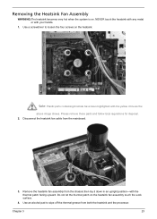
Chapter 3 23 Use a screwdriver to wipe off the thermal grease from the mainboard. 3. Remove the heatsink fan assembly from the chassis then lay it down in an upright position-with your hands. 1. NEVER touch the heatsink with any ...
Chapter 3 23 Use a screwdriver to wipe off the thermal grease from the mainboard. 3. Remove the heatsink fan assembly from the chassis then lay it down in an upright position-with your hands. 1. NEVER touch the heatsink with any ...
Service Guide
Page 32
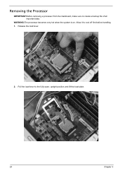
Release the load lever. 2. Allow it to create a backup file of all important data. Removing the Processor IMPORTANT:Before removing a processor from the mainboard, make sure to cool off first before handling. 1. Pull the load lever to the fully open, upright position and lift the load plate. 24 Chapter 3 WARNING:The processor becomes very hot when the system is on.
Release the load lever. 2. Allow it to create a backup file of all important data. Removing the Processor IMPORTANT:Before removing a processor from the mainboard, make sure to cool off first before handling. 1. Pull the load lever to the fully open, upright position and lift the load plate. 24 Chapter 3 WARNING:The processor becomes very hot when the system is on.
Service Guide
Page 35
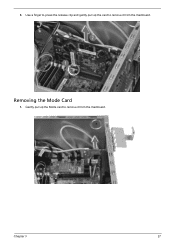
Removing the Mode Card 1. Gently pull up the card to remove it from the mainboard. 3. Chapter 3 27 Use a finger to press the release clip and gently pull up the Mode card to remove it from the mainboard.
Removing the Mode Card 1. Gently pull up the card to remove it from the mainboard. 3. Chapter 3 27 Use a finger to press the release clip and gently pull up the Mode card to remove it from the mainboard.
Service Guide
Page 36
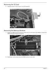
Release the DIMM module by pressing the holding clips (1) on both sides of the DIMM slot. Repeat step 1 until you have removed all DIMM modules from the slot. 2. Gently lift the DIMM module (2) to remove it from their slots. 28 Chapter 3 Gently pull up the TV card to remove it from the mainboard. Removing the TV Card 1. Removing the Memory Modules 1.
Release the DIMM module by pressing the holding clips (1) on both sides of the DIMM slot. Repeat step 1 until you have removed all DIMM modules from the slot. 2. Gently lift the DIMM module (2) to remove it from their slots. 28 Chapter 3 Gently pull up the TV card to remove it from the mainboard. Removing the TV Card 1. Removing the Memory Modules 1.
Service Guide
Page 38
Remove the HDD bracket a. Disconnect the data cables from the mainboard. 4. Remove the screw that secures the HDD bracket to the chassis. 30 Chapter 3 3.
Remove the HDD bracket a. Disconnect the data cables from the mainboard. 4. Remove the screw that secures the HDD bracket to the chassis. 30 Chapter 3 3.
Service Guide
Page 40
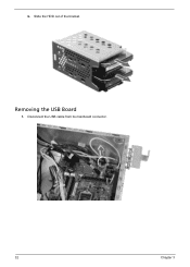
Removing the USB Board 1. b. Slide the HDD out of the bracket. Disconnect the USB cable from its mainboard connector. 32 Chapter 3
Removing the USB Board 1. b. Slide the HDD out of the bracket. Disconnect the USB cable from its mainboard connector. 32 Chapter 3
Service Guide
Page 45
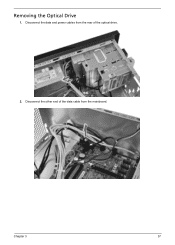
Disconnect the other end of the data cable from the rear of the optical drive. 2. Chapter 3 37 Disconnect the data and power cables from the mainboard. Removing the Optical Drive 1.
Disconnect the other end of the data cable from the rear of the optical drive. 2. Chapter 3 37 Disconnect the data and power cables from the mainboard. Removing the Optical Drive 1.
Service Guide
Page 48
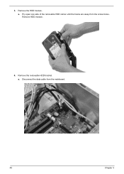
Remove HDD module. 4. Disconnect the data cable from the screw bores. Remove the removable HDD bracket. a. a. Pry open one side of the removable HDD carrier until the hooks are away from the mainboard. 40 Chapter 3 Remove the HDD module. 3.
Remove HDD module. 4. Disconnect the data cable from the screw bores. Remove the removable HDD bracket. a. a. Pry open one side of the removable HDD carrier until the hooks are away from the mainboard. 40 Chapter 3 Remove the HDD module. 3.
Service Guide
Page 51
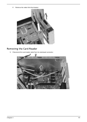
Chapter 3 43 Removing the Card Reader 1. Disconnect the card reader cable from the bracket. f. Remove the cable from its mainboard connector.
Chapter 3 43 Removing the Card Reader 1. Disconnect the card reader cable from the bracket. f. Remove the cable from its mainboard connector.
Service Guide
Page 55
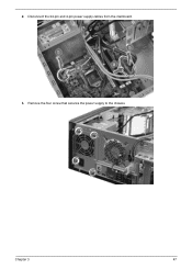
Remove the four screw that secures the power supply to the chassis. Chapter 3 47 Disconnect the 24-pin and 4-pin power supply cables from the mainboard. 3. 2.
Remove the four screw that secures the power supply to the chassis. Chapter 3 47 Disconnect the 24-pin and 4-pin power supply cables from the mainboard. 3. 2.

Service Guide
Page 56
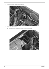
Disconnect the remaining cables from the mainboard. 48 Chapter 3 Lift the power supply module out of the chassis. Removing the Mainboard 1. 4.
Disconnect the remaining cables from the mainboard. 48 Chapter 3 Lift the power supply module out of the chassis. Removing the Mainboard 1. 4.
Service Guide
Page 57
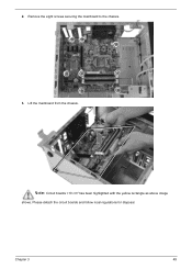
Chapter 3 49 Note: Circuit boards >10 cm² has been highlighted with the yellow rectangle as above image shows. 2. Please detach the circuit boards and follow local regulations for disposal. Lift the mainboard from the chassis. Remove the eight screws securing the mainboard to the chassis. 3.
Chapter 3 49 Note: Circuit boards >10 cm² has been highlighted with the yellow rectangle as above image shows. 2. Please detach the circuit boards and follow local regulations for disposal. Lift the mainboard from the chassis. Remove the eight screws securing the mainboard to the chassis. 3.
Service Guide
Page 68
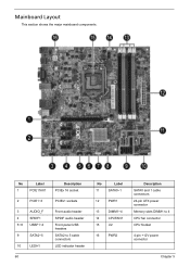
No Label 1 PCIE116X1 2 PCIE1~3 3 AUDIO_F 4 SPDIF1 5~8 USBF1~4 9 SATA2~5 10 LEDH1 60 Description PCIEx 16 socket PCIEx1 sockets Front audio header SPDIF audio header Front panel USB headers SATA2 to 5 cable connectors LED indicator header No Label 11 SATA0~1 12 PWR1 13 DIMM1~4 14 CPUFAN1 15 U2 16 PWR2 Description SATA0 and 1 cable connectors 24-pin ATX power connector Memory slots DIMM1 to 4 CPU fan connector CPU Socket 4-pin +12V power connector Chapter 5 Mainboard Layout This section shows the major mainboard components.
No Label 1 PCIE116X1 2 PCIE1~3 3 AUDIO_F 4 SPDIF1 5~8 USBF1~4 9 SATA2~5 10 LEDH1 60 Description PCIEx 16 socket PCIEx1 sockets Front audio header SPDIF audio header Front panel USB headers SATA2 to 5 cable connectors LED indicator header No Label 11 SATA0~1 12 PWR1 13 DIMM1~4 14 CPUFAN1 15 U2 16 PWR2 Description SATA0 and 1 cable connectors 24-pin ATX power connector Memory slots DIMM1 to 4 CPU fan connector CPU Socket 4-pin +12V power connector Chapter 5 Mainboard Layout This section shows the major mainboard components.
Service Guide
Page 82
Category Part Name FRONT BEZEL M350 W/POWER LED CABLE FRONT BEZEL M351 W/POWER LED CABLE Description FRONT-BEZELASSY-M350 FRONT-BEZELASSY-M351 Acer Part No. 60.SF701.002 60.SDZ01.006 CRT COVER HDMI DUMMY COVER ASSEMBLY MAIN CHASSIS W/ MB SUPPORT ASSY & TOP IO ASSY & TOP RIGHT SIDE ...COVER CVR CRT BOXER II HDMIC-1 MAIN CHASSIS ASSY M3 42.SF601.001 42.SF601.002 60.SF701.001 COMBO MODULE CPU/PROCESSOR MAINBOARD SUPPORT TOP RIGHT SIDE COVER TOP IO W/F-IO BOARD ODD PIONEER BD COMBO SATA HH HF+W7 6X HLDS CH20N W/BEZEL BLACK ODD PLDS BD...
Category Part Name FRONT BEZEL M350 W/POWER LED CABLE FRONT BEZEL M351 W/POWER LED CABLE Description FRONT-BEZELASSY-M350 FRONT-BEZELASSY-M351 Acer Part No. 60.SF701.002 60.SDZ01.006 CRT COVER HDMI DUMMY COVER ASSEMBLY MAIN CHASSIS W/ MB SUPPORT ASSY & TOP IO ASSY & TOP RIGHT SIDE ...COVER CVR CRT BOXER II HDMIC-1 MAIN CHASSIS ASSY M3 42.SF601.001 42.SF601.002 60.SF701.001 COMBO MODULE CPU/PROCESSOR MAINBOARD SUPPORT TOP RIGHT SIDE COVER TOP IO W/F-IO BOARD ODD PIONEER BD COMBO SATA HH HF+W7 6X HLDS CH20N W/BEZEL BLACK ODD PLDS BD...

